|
Lafayette KT-135 EXPLOR-AIR radio
kit |
 |
|
|
|
|
|
|
Click on photo for larger version. |
| This 1960 Lafayette catalog
page states "the chassis is
completely isolated from the circuit, so there is no
shock hazard." (Thanks to Jim Hale for catching this.) |
|
|
|
|
|
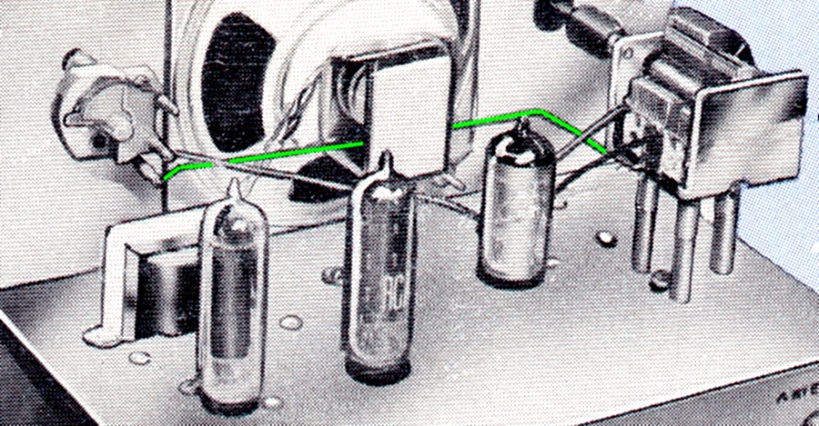
| This could be accomplished
if nylon screws and standoffs were used for the
tuning capacitors and a few extra wires were added,
which seems to be what they did. The green wire
shown above, connecting the two tuning capacitors
together, does not exist in any KT-135 I have ever
seen. |
|
|
|
|
|
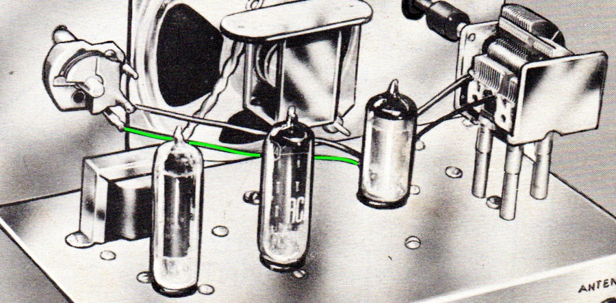
In this rendering from the actual the construction manual, the wire
enters the hole in the chassis behind the 12AT7.
The frame of the main tuning capacitor is connected to the
chassis with metal standoffs and doesn't need the third
wire. |
|
|
|
|
|
|
|
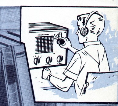
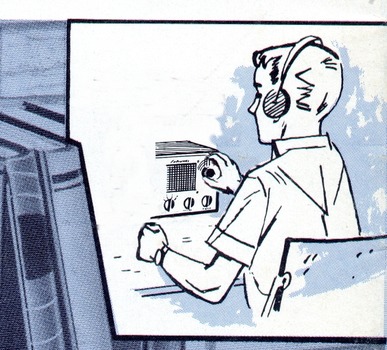
Truth in advertising! How it appears in
the ad and how it would actually look.
Notice the radio is the white version shown on the previous
pages. |
|
|
|
|
|
|
|
|
Here's an ad from 1961. It, too, states
the chassis is completely isolated from the circuit. (Click
on the ad for a larger version.)
All of these early
catalog entries state that the KT-135 picks up
satellite signals. This is probably a reference to
the Russian Sputnik 4 and Sputnik 5 satellites,
launched in May and August 1960, which could be
heard on 19.996 Mhz in the 10 meter band (Band D on
the KT-135). This claim was dropped in 1964. |
|
|
|
|
|
|
|
|
|
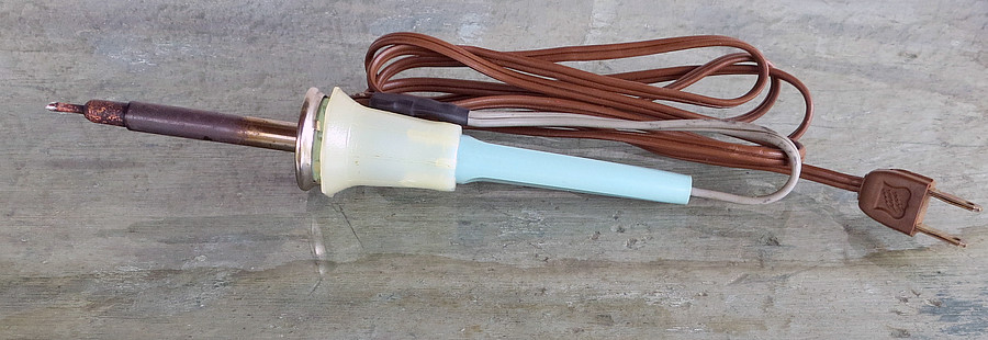
| I replaced the cord on my
soldering iron with an old KT-135 cord after I
melted the old cord while not paying attention. |
|
|
|
|
THE SCHEMATIC |
|
|
|
|
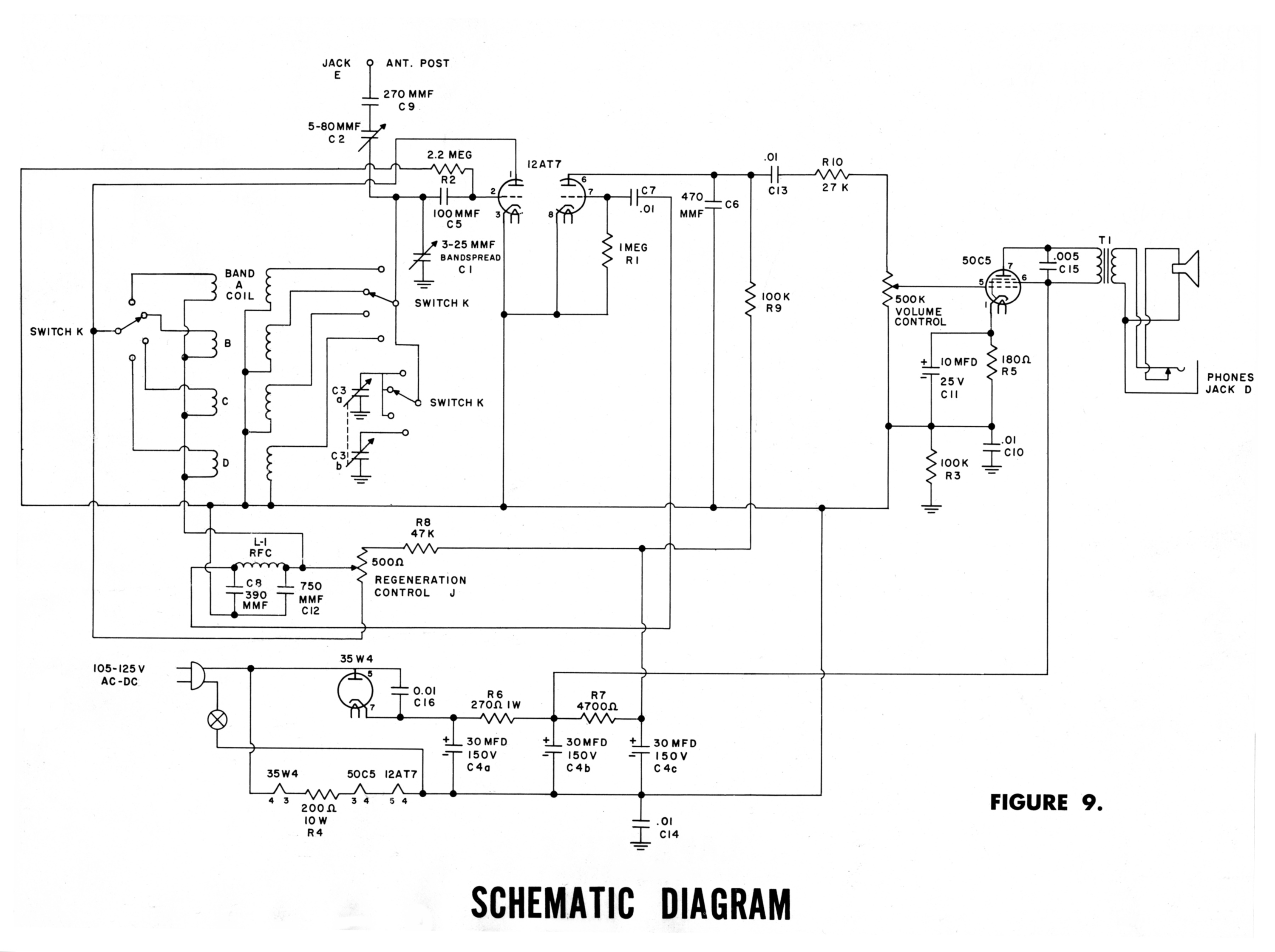
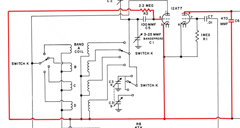
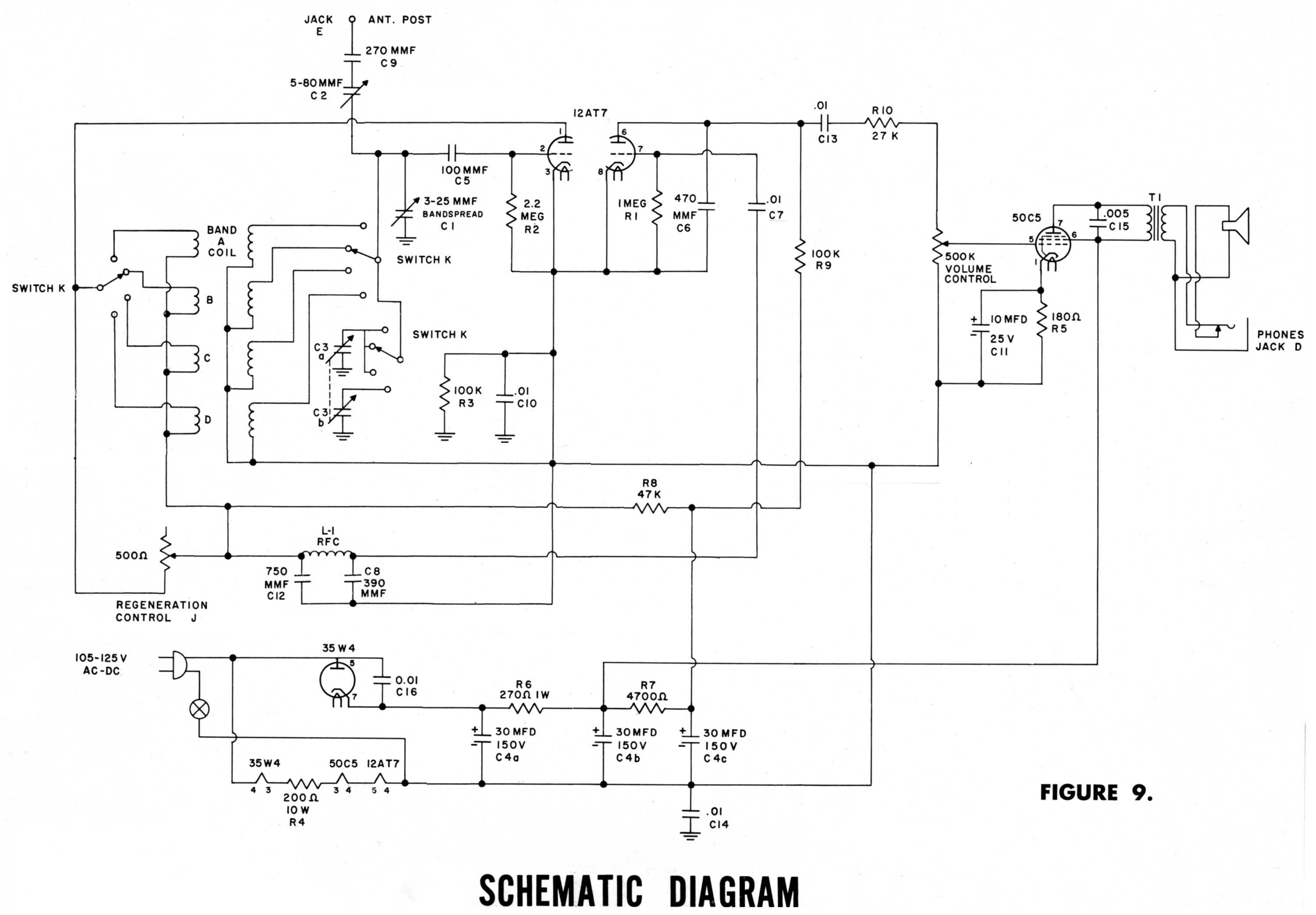
| This is the
schematic diagram from the assembly manual. A schematic
doesn't normally represent how the parts are
physically assembled, but I was confused by some of
it. (Click on the diagram to open a larger version.) |
|
|
|
|
|
|
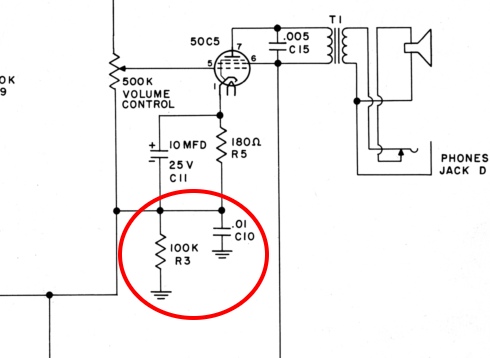
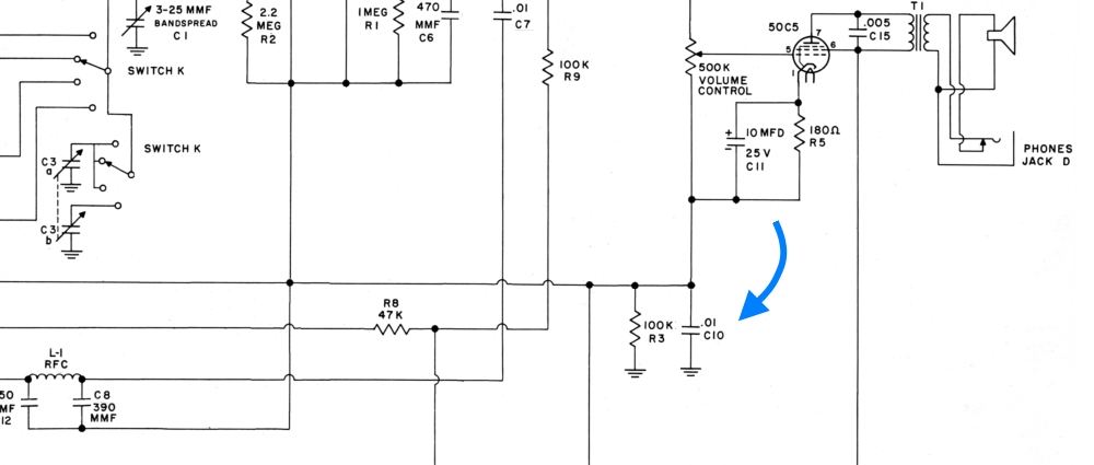
Let's see how these highlighted parts are rendered in the
schematic. |
|
|
|
|
|
|
|
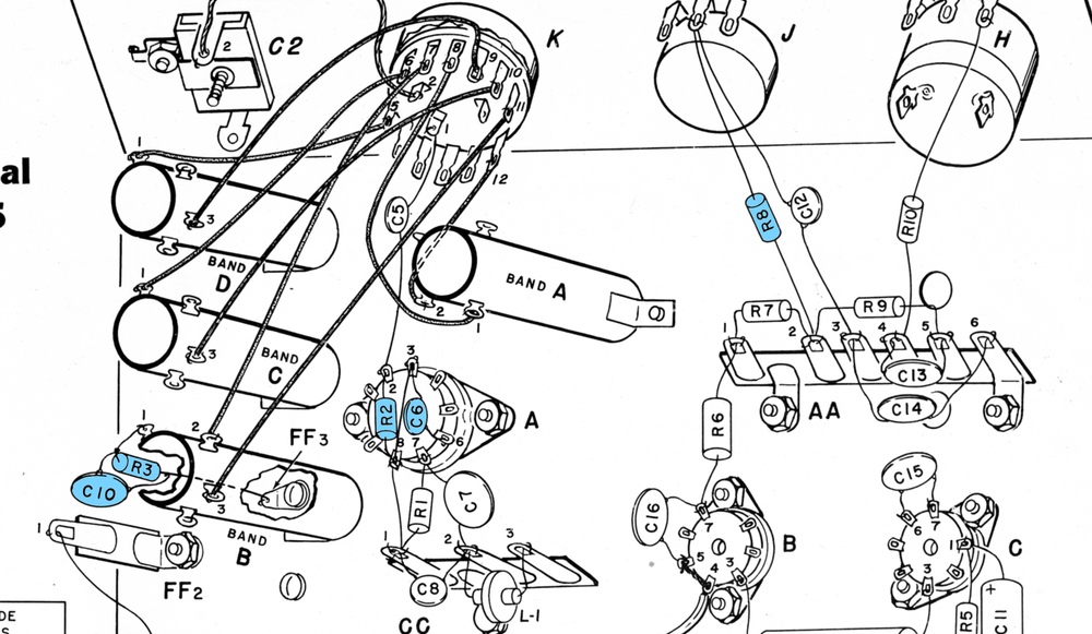
R3 and C10 appear to be connected
to the 50C5 vacuum tube on the schematic, but they are physically
connected to lug 1 of the coil for band B, on the
opposite side of the radio!
The symbol with
the tapered horizontal lines designates that one side of R3
and C10 are connected to the chassis, ergo one side
is soldered to a lug that is
screwed to the chassis. They have nothing to do with
the 50C5 vacuum tube, it only appears that way at
first glance. |
|
|
|
|
|
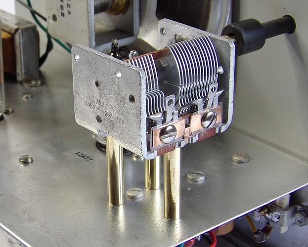
| The main tuning capacitor is
connected to the chassis with metal screws and
standoffs. R3 and C10 are
actually connected directly to the tuning capacitor with a
soldering lug to one of the screws that hold it to
the chassis. A terminal on the B coil is used to
pick up the B minus. |
|
|
|
|
|
R3 and C10 are used to connect the tuning capacitor to B
minus by way of the metal chassis. They also isolate
the tuning capacitor and the chassis from the
110 volts AC. Let's move them to avoid confusion. There was nothing "wrong" with
the original schematic, but now the components don't
appear to be part of the 50C5 hookup.
If you
examine the full schematic you'll notice that C14
(all the way on the bottom) and C10 have the same
connections. You could use a .02 mfd capacitor as
C14 and just omit C10, or vise versa. |
|
|
|
|
|
|
|
|
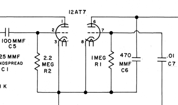
| On the left is
resistor R2 and capacitor C6 soldered to the bottom
of the 12AT7 tube socket. Look how they are drawn in
the schematic. |
|
|
|
|
|
Why wasn't it
drawn like this instead?
|
|
|
|
|
|
|
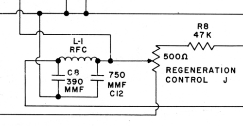
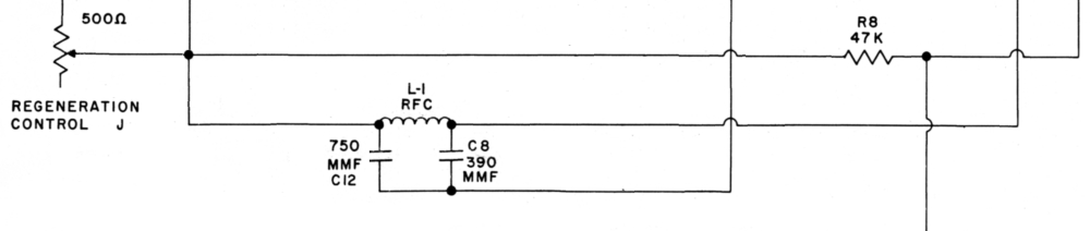
| This shows the regen control and the RF choke.
The schematic (left picture) has R8 connected to the
wrong terminal on the
regen control. |
|
|
|
|
|
|
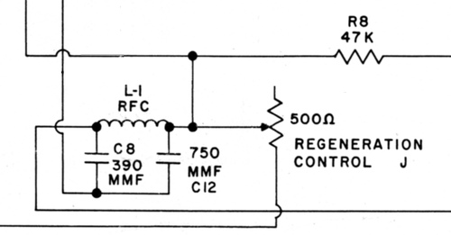
Here the connection to R8 is fixed, the choke connections are flipped
and the regen control is moved,
making the diagram easier to follow. |
|
|
|
|
|
|
|
|
|
| The
corrected and rearranged schematic. (Click for larger
version) |
|
|
|
|
THE ROTARY SWITCH (SWITCH K) |
|
|
|
|
|
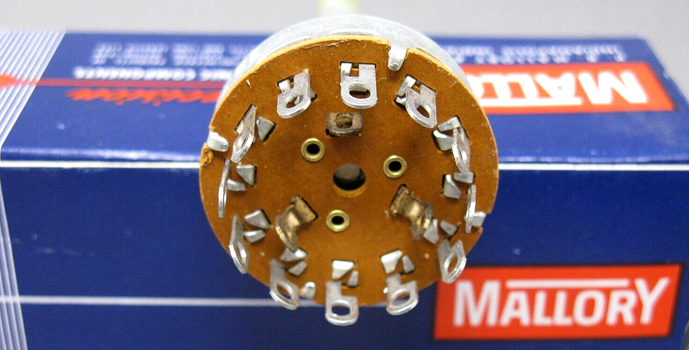
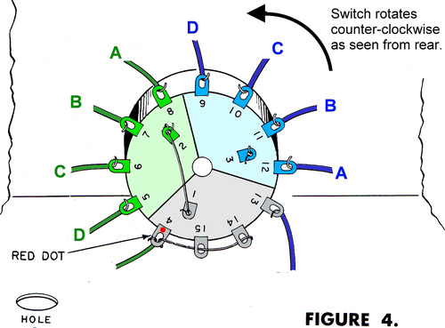
The rotary switch is a 3
pole, 4 position non-shorting type (3P4T). A similar
switch was made by Mallory, part number 3234J. These
are still available online. The prices range from $4
to $45 for the same switch, so watch out for the
crack smokers. |
|
|
|
|
|
|
|
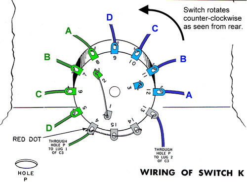
The wiring of the switch looks
confusing, but you can visualize it as three
separate switches that move in unison. Notice that lug 1 is tied
to lug 2. This connects the coils to the tuning
capacitor via lugs 4, 15, and 14, except that on Coil D, lug
13 connects to the smaller gang of the tuning
capacitor. |
|
|
|
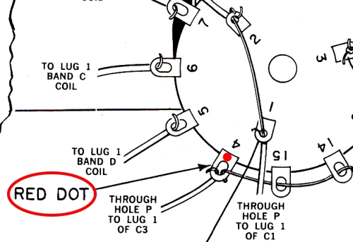
The
red dot is important. If
you have replaced the switch you need to
know where to start wiring. The first
outer connection made to the switch as you're building
the radio is to lug 4. The instructions don't specify
how to mount the switch, but the drawings clearly
show a red dot.
If you have removed the
switch while rebuilding the radio and can't find the
red dot, can you rely on the drawing? Yes, there is
a little tab on the front of the switch which goes
into a hole in the chassis. if you mount the switch
oriented the way it is in the drawing, lug 1 will be
on the bottom and lug 4 will be below and to
the left of lug 1. |
|
|
|
|
|
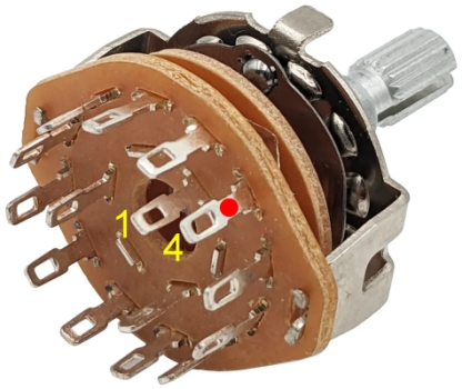
If you're replacing the switch
with a different type, do this: Turn the switch
counter-clockwise as far as it will go. Select one
of the inner terminals on the back. This will be lug
1. Use an ohmmeter or continuity tester and find the
outer terminal that shows a
connection to lug 1. This will be lug 4. Mark it
with a red
dot. If you're colorblind to the color red, mark it
with a different color or people will think you're
lying about being colorblind. |
|
|
|
|
|
|
|
|
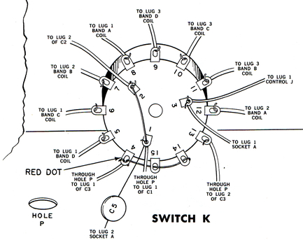
Here are the switch
designations on the schematic (since Lafayette
didn't add them). As far as the numbering system is
concerned, it seems the designer selected
lug 4 (with the red dot) and then went around the
switch clockwise. This put the numbers out of order
at Lug 1.
It didn't really matter. Not a
single person ever used the schematic to wire the
switch. It is merely presented here so you can bring
it up on your phone at the start of a party to break the ice. |
|
|
|
|
|
|
|
|
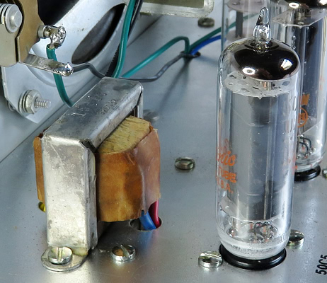
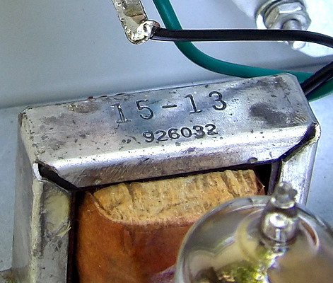
The audio output transformer has
the number 15-13 stamped on the top, which is also the
part number of the transformer in the KT-135
assembly manual. What are the odds?
The primary winding has a DC resistance of
166 ohms and the secondary of approximately 1.5
ohms. The distance between the mounting holes is two
inches. There are two other numbers on the
transformer but none of them correspond to anything
in the Lafayette catalogs from that era. If you need
to replace it, it may be easier to find a junk radio
that used a 50C5 output tube, and scavenge it.
The
50C5 output tube has a load resistance of about 1800
to 2400 Ohms at maximum output, and the
KT-135 speaker is rated at 4 Ohms. If you are trying to
locate a (new) replacement transformer, look for one
with those approximate specs. For example, in this
crop from the 1970 Lafayette catalog, a transformer
has a primary impedance of 2,000 Ohms and a secondary of 4 Ohms.
The mounting holes are 2" apart. This is perfect.
Note that these values are impedance and not DC
Ohms.
|
|
 |
|
The primary side of the
transformer usually has red and blue leads. The red
lead is always connected to B+. In the case of the
KT-135, this is pin 6 of the 50C5. |
|
|
|
|
|
Next, some other Lafayette KT-135 kits restored or
refurbished.. |
| |
|
|
| |