|
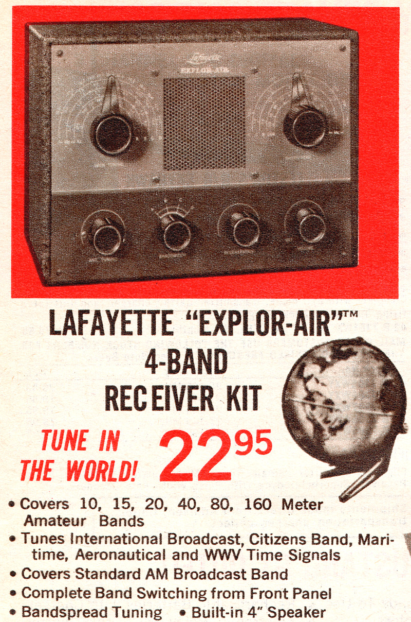
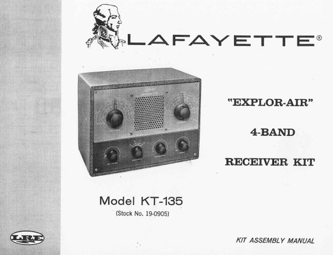
Lafayette KT-135 EXPLOR-AIR radio
kit |
 |
|
|
|
|
|
|
|
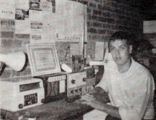
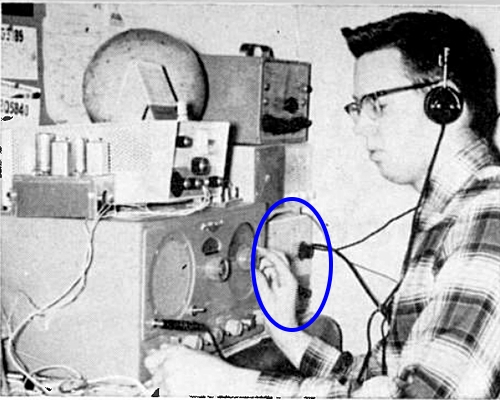
In the 1960s, Popular Electronics
hosted a monthly column called "Short Wave Listening."
Occasionally a KT-135 would appear in the photos. On the
left is Mike Byers of Shelby, NC whose primary receiver was
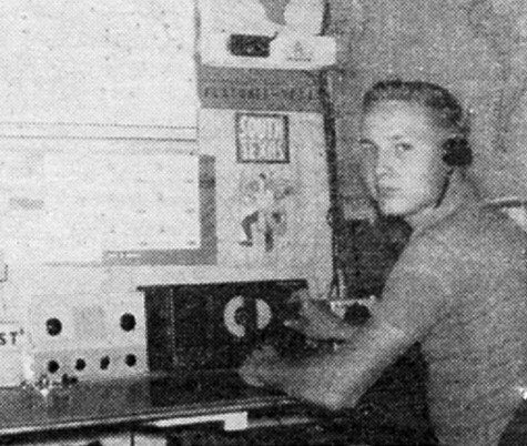
a Lafayette KT-135 (from October 1965 issue.) The photo on
the right, from August 1964, shows Robert Mladenka of
Flatonia, Texas, whose "backup" receiver was a Lafayette
Explor-Air.
Notice the newer style knobs on Mike Byers' 1965 KT-135. |
|
|
|
|
|
|
|
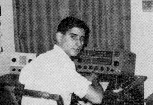
From Electronics Illustrated,
November, 1963.
This is John Sullivan of Greenwich,
Connecticut. He's operating a
Hallicrafters S-120, but you
can see he started with a KT-135. |
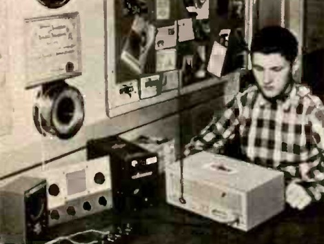
From Popular Electronics, September, 1964.
Edward Jacobson of Westbury, NY is using a Lafayette HE-30
receiver,
with his KT-135 in "standby service." The HE-30
was also a kit. |
|
|
|
|
|
|
|
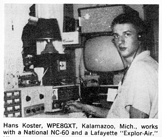
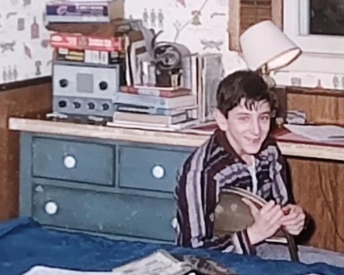
Gary Confrey of Killingworth,
Connecticut.
A Lafayette KT-135 sits on top of a Lafayette "Starflite"
transmitter.
Photo from the May, 1966 issue of Popular Electronics. |
Listening post of Grant Power, VE2PE6K of
Montreal, Canada.
For some reason he isn't in the photo, but the KT-135 is.
Photo from September, 1963 issue of Popular Electronics. |
|
|
|
|
|
|
|
Popular Electronics, July 1969. |
Popular Electronics, May 1968. |
|
|
|
|
|
Popular Electronics, November, 1963.
Grant Power, VE2PE6K, in Montreal, Quebec. |
Dan Levine, WA2CLP, in 1967 |
|
|
|
|
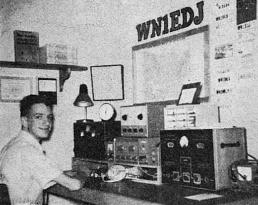
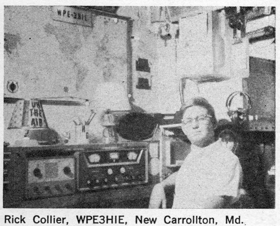
The call signs that started with the designation
"WPE" were issued by Popular
Electronics to shortwave listeners. |
|
|
|
It is interesting to see the faces
of people who built a KT-135. Makes you wonder what happened to
them. Not the people, the radios! Well, the people, too, I
guess.
Gary Confrey was about 15 years old in the photo above. The
KT-135 was his first kit, purchased at the Lafayette store
in New Haven, Connecticut. (The Starflite transmitter was
also a kit.) The KT-135 got him started in electronics and
he spent his life in that field. As of 2022 he is 72 years
old and a senior technician in a lab at an electronics
company. He is still an Amateur radio operator and lives in
Monroe, GA.
Dan Levine is still a Ham. I can't find
any information on the other people in the pictures. |
|
|
|
|
|
|
|
|
|
From spring 1969 catalog. |
|
|
|
|
REPAIR NOTES AND TIPS CONCERNING THE
KT-135 |
|
|
|
|
|
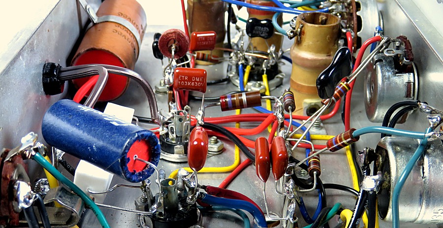
| A rebuilt KT-135. |
| Lafayette claimed that the KT-135 is
so easy to build a child who can read could do it. This is
marketing BS. Building or rebuilding a KT-135 is
NOT easy. Some were built by a 10
year olds, but that doesn't mean it's a piece of cake because you're
not 10. However, the instructions are practically
fool-proof. Any wiring mistakes or a component installed of
the wrong value will be picked up later in the assembly. |
|
|
|
|
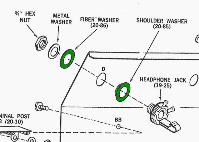
The Headphones Jack |
|
|
|
|
Notice the fiber and
shoulder washers on the headphone jack. They are
both made of the same fiber material and insulate
the headphone jack from the chassis. I've found two
sets with the shoulder washer missing. Without the
shoulder washer, the common side of the headphone
jack is connected to the chassis, which means that
one side of the speaker and audio output transformer
are also connected to the chassis.
Depending on how the non-polarized plug is inserted
into the outlet, the chassis could be "hot." When the chassis is "hot" it's sitting
at 94 VAC in reference to earth ground. Without the
shoulder washer the headphone jack is now also
"hot." The current is limited by a 100K
resistor, so it won't kill you, but what would it do
to your headphones? |
|
|
|
If necessary, you can use the fiber washer from
the antenna connector as the shoulder washer
for the headphone jack, since the antenna connector is plastic and
has a shoulder molded into it.
|
|
|
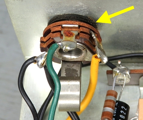
Noisy Antenna Tuning Capacitor |
|
|
|
|
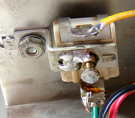
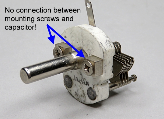
The Antenna Tune capacitor
can be very noisy. This one was so
noisy it was ruining the reception. It also wobbled
and the knob looked crooked.
The capacitor is a standard compression type, mounted in a bracket. The bracket is grounded to
the chassis. It has a 1/4 " diameter shaft attached to a
screw that projects through a brass threaded collar.
The value is 5 to 80 mmfd. In series with the
variable capacitor is a disc capacitor with a value
of 270 mmfd. This causes the total value to be 3 to
25 mmfd.
The capacitor is totally isolated from the chassis
bracket and it can't go intermittent or short out by
the nature of its construction. So what is causing
the problem? It's the
connection between the mounting bracket and the brass collar!
An ohmmeter was connected between the chassis and
the collar, and the meter swung wildly when the knob
on the front was turned.
So what? There is no connection to the actual
capacitor. Apparently, since this is
where the antenna comes in, the intermittent causes
a small electric current that the antenna picks up
and is then
amplified thousands and thousands of times. That's
my theory, at least. If you unscrew the capacitor
from the chassis and let it hang in the air, the
problem goes away. |
|
| |
|
|
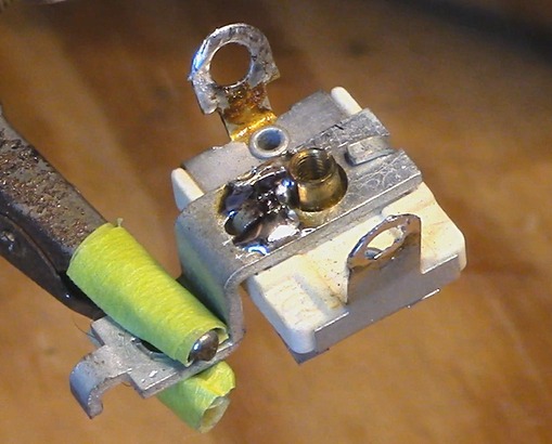
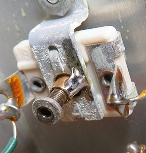
| The fix is to polish up part
of the brass collar and the mounting bracket (I used
a knife to scratch it up) and connect the bracket to the collar with
a blob of solder. This also stiffens the capacitor in
the bracket so it won't wobble. Don't solder the
screw to the brass collar! |
|
| |
|
|
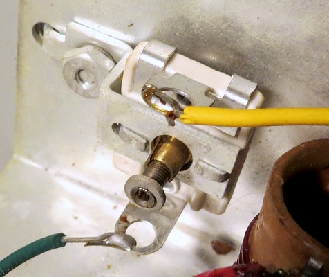
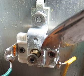
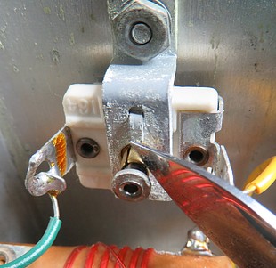
| In the left photo the
threaded shaft has been removed because it was bent. On the right is
the same capacitor put back in service. |
| |
|
|
| Scrape the steel
bracket, scrape the brass collar, then solder them together. I have
a 100% success rate with this fix. |
|
|
|
|
|
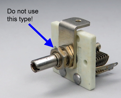
| If you are going to replace the antenna tune
capacitor, be sure to isolate it from the chassis
and do not allow the shaft to come into contact with
the front panel. Do not use the type that mounts to
the front panel using a nut around the threaded base
of the shaft. |
|
|
|
|
|
Loud Hum. Rebuild The Filter Capacitor. |
|
|
|
|
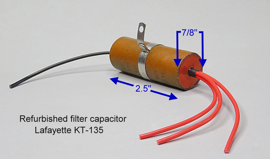
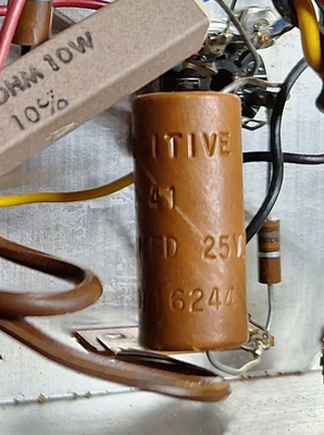
The KT-135 uses three power
supply filter capacitors encased in a single
cardboard tube, Lafayette part number 12-59. They are
each rated 30 MFD at 150 volts. After 65 years or
so, none of them work as they should, causing a loud
hum in the radio.
|
|
|
|
The filter capacitor bundle is
encased in plastic. To remove it from its housing it
is necessary to use a heat gun. You must get it very
hot. Put the three red wires in a vise and heat it
evenly with the heat gun. When it looks like it's
"sweating" it's almost ready. Grab the capacitor
using a rag (NOT YOUR BARE HAND) and pull gently.
If nothing happens, stop and apply more heat, but
don't scorch it or start the thing on fire. When
it's hot enough the casing will pull off, leaving
the guts hanging out of the vise on the three red
wires.
When you realize how hot the capacitor needs to get
before the plastic melts, you'll wonder how it
survived being encased in the molten plastic to
begin with. How did they inject the hot plastic into
the cardboard tube? |
|
|
|
|
|
|
|
|
| The three capacitors are
made of layers of metal foil insulated with paper,
rolled up very tightly. The negative side is a
single piece of aluminum foil approximately 33
inches long and 1.5 inches wide. Three 10.5 inch
strips of metal make up the positive sides. The paper should be damp or
sticky with electrolyte, but in almost every case it
is
bone dry due to age. |
|
|
|
|
|
|
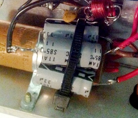
| Three 33uF caps rated at 160
volts may fit perfectly
inside the casing, and the voltage rating is higher
than the original 150 volts. 250 volt caps won't fit. Observe
the polarity carefully. A modern filter capacitor
connected backwards will be instantly destroyed when
power goes through it. |
|
|
|
|
|
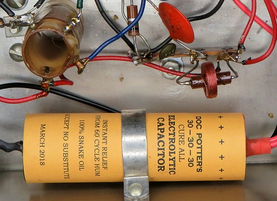
| Use cardboard disks at
either end, push everything into the empty casing,
then seal the ends. I used pieces of beeswax (not
paraffin), and heated it with a
soldering iron
to melt it. Hot glue works, and 5 minute epoxy does a very nice job
and makes the capacitor look like it's right from the factory. Several layers of white glue
(it dries somewhat clear) creates a nice appearance, and is the easiest and cheapest
method. |
|
|
|
|
| If you acquired a set where
the capacitor has already been replaced you can just
make your own. Instead of trying to find capacitors
to fit the cardboard tube, find a cardboard
tube to fit the capacitors. Be sure to make a nice
label. These were printed on a manila envelope to
save ink. The one on the right states that inside is
100% SNAKE OIL |
|
|
|
|
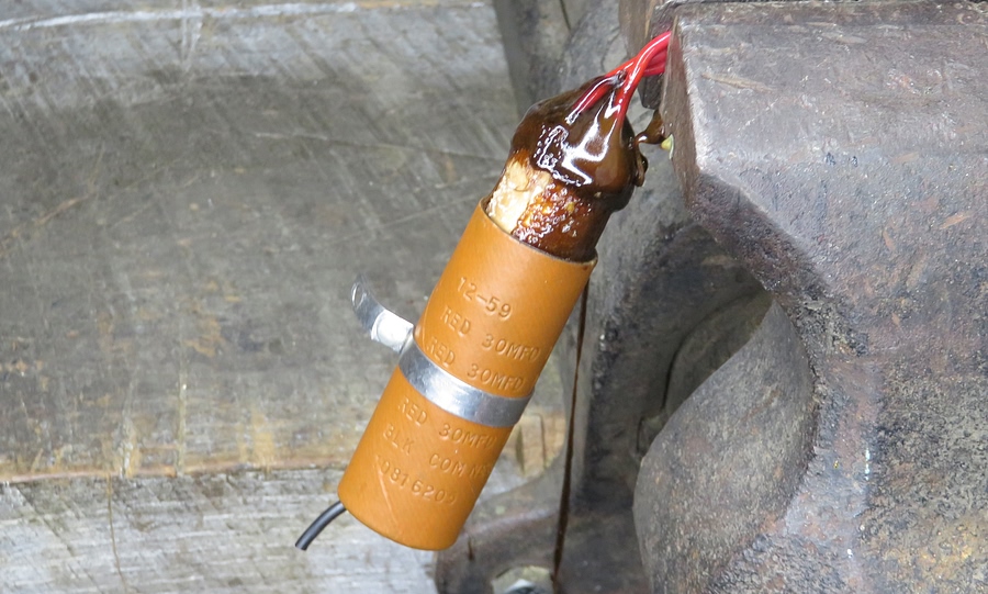
| OK, have it your way. Safety first
and all that. At least make them look nice,
not like the dangerous mess in the photo on the right. |
|
|
| NOTE: With the radio on and
volume turned all the way down, the radio has a
slight 60 cycle hum. There is nothing wrong with the
radio
or your new filter capacitors. |
|
|
|
|
All the capacitors and resistors needed to restore
your radio can be found at
justradios.com.
If you need tube sockets or other
components, try
radiodaze.com. |
|
|
|
|
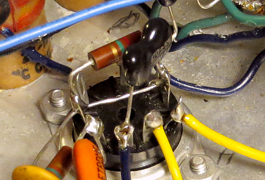
Stations drift, regeneration
requires constant tweaking |
|
|
|
|
|
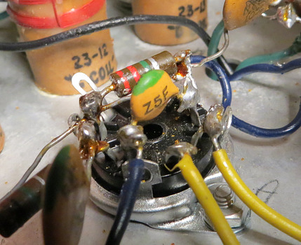
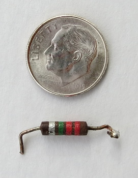
| These pictures, of two
different radios, show the underside of the 12AT7
tube socket, the 2.2 meg grid leak
resistor (R2) and the 470 pF capacitor (C6). The
leads are very short but somehow survived the heat
from the soldering iron. As the tube heats the
resistor and the capacitor, the
values of these components will change, causing a
change in
performance. |
|
|
|
|
|
To improve the radio, replace the resistor and
capacitor. Get the resistor away from the socket
and use a silver mica capacitor. Silver mica caps
are basically immune to temperature
change. Don't attempt this without a spare tube
socket at hand, unless you are very brave. You will
also need to cut some of the blue wires going to the
band switch control to get to the socket.
Don't forget to take the tube out of the socket
before you start working on it. |
|
|
|
|
|
|
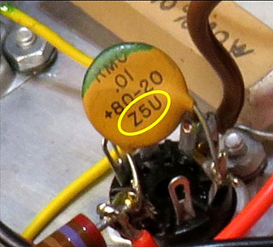
Note:
The capacitors in the KT-135 have two ratings. Most
are rated Z5U. The value of these capacitors is
sensitive to temperature change and can vary as much
as 50% between 50F and 185F.
The capacitor
across the 12AT7 is rated Z5F. This rating signifies the
value is much more precise and there is little
change with temperature (only about 7.5%). However,
a mica capacitor is even more precise and resistant
to temperature change. |
|
|
|
|
|
|
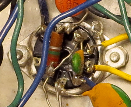
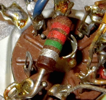
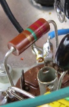
| The value of this 2.2 meg
resistor was actually over 5 meg after being cooked
by the soldering iron. You can tell it's bad just by
looking at it. Guess who did that. ME. This is my
KT-135 from 1972. The radio worked anyway! In the
center photo the resistor has been replaced. The
instructions say to cut each lead to 1/2 inch long.
Cut them to 3/4 of an inch long instead. |
|
|
|
|
|
Low audio volume, but 50C5 tube tests OK. |
|
|
|
|
|
|
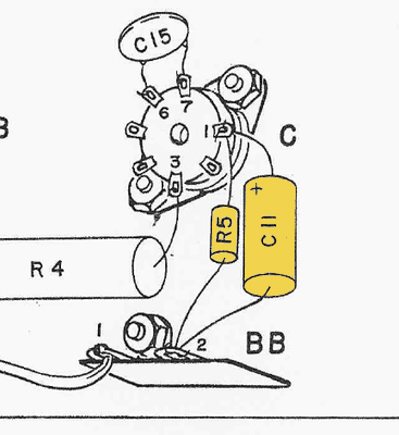
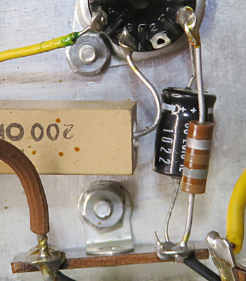
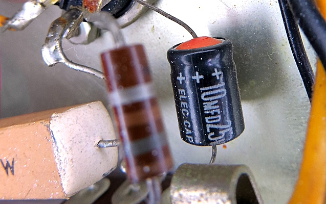
|
Replace capacitor C11 with a new 10mfd
electrolytic. While it's out, make sure resistor R5 is still
around 180 ohms. |
|
|
|
This
swollen capacitor, from a KT-135 built in 1966, is now 400%
out of tolerance. |
|
|
|
Radio will not oscillate,
regeneration control doesn't seem to work.
Weak 12AT7 |
|
|
| If the
12AT7 drops below 25% of its rating, the radio will
not break into regeneration no matter how high the
regen control is set. |
|
|
|
|
|
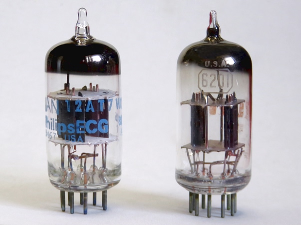
A Phillips
JAN 12AT7 and an RCA 6201.
|
A 12AX7 was
sold with the KT-135 from 1959 to 1961. After 1961 a
12AT7 was used. It's easier to control the
regeneration with a 12AT7.
Another designation for the
12AT7 is ECC81. If you find a tube marked "JAN", the
designation stands for "Joint Army Navy." The
12AT7 JAN may be superior, as
well as cheaper.
The 12AT7W, 12AT7WA, and 6201 are ruggedized against
vibration. GE, Sylvania and Tung-Sol made a version
labeled 6679 which was resistant to fluctuations in
voltage. The CV4024 is a
12AT7 made for the British military. All of
these work perfectly.
Stay away from modern
Russian and Chinese versions, as they don't meet the
specifications of a 12AT7. |
|
|
|
|
|
|
|
|
|
|
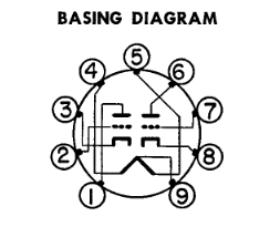
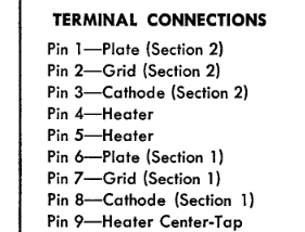
Above is the pinout of
the 12AT7 / 6201. It is
shown as though you were looking at the bottom
of the tube. If the pins on the left are designated 1, 2 and 3,
why is it considered triode 2 and not triode 1?
The answer, which is not an answer, is that the
Radio Electronics Television Manufacturers
Association (RETMA) said triode 1 shall be on
pins 6, 7 and 8. What? WHY? Now I'll never get
to sleep!
The regenerative detector
section of the KT-135 is on pins 1, 2 and 3. If
you test the tube in a tube tester, the 2nd
triode is the important one! |
|
|
|
|
|
|
|
|
Replacing the power cord |
|
|
|
|
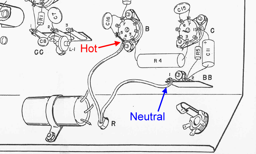
A new power cord will be
polarized. The wide prong is "Neutral" and the
narrow prong is "Hot". (Very useful to know when
rewiring a lamp!) The Neutral wire has a thin stripe
molded into the rubber so you know which wire it is.
Page 16 of the instructions say to turn the
Explor-Air on, then plug it in. Without touching any
part of the radio, check for a voltage between the
chassis and ground. If a voltage is detected,
reverse the plug. Make sure the meter is set to
"AC."
To wire it correctly so that no voltage is present
in the chassis while the unit is on, observe the
picture above. Note that the instructions specify
the set must be ON while checking for voltage. When
plugged in correctly, you'll get no voltage while
the set is on, but you WILL get a voltage while the
set is OFF. However, this voltage won't be directly
from the AC outlet, it has to go through several
capacitors before it gets
to the chassis. |
|
|
|
|
|
If the new cord is thicker
than the original, carve some of the plastic out of
the strain relief to make it fit. That way, you
don't chew it up with the pliers trying to get it
back in the chassis.
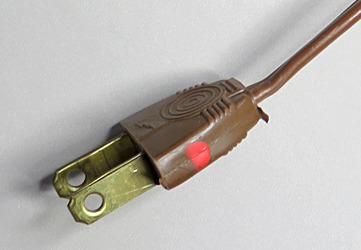
If the old cord is in good
condition you can just follow the instruction in the
manual to mark the "hot" side of the plug. This
side goes into the narrow slot of the AC outlet. (If
the outlet is non-polarized, you will have to mark
it as well.) I
used red paint because a year later I'd forget and
think, "Dolp, I wonder what that dot means." Now
I can just think "red hot." |
|
|
|
|
|
|
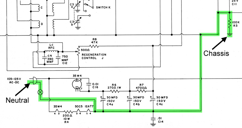
Basically, the plug will be
wired as above. If it's wired the other way, the hot
side of the AC outlet will be connected to the
chassis via the 100K resistor, and you will feel a
mild electric shock if
you touch it while grounded.
This is not a "hot chassis" where one
side of the AC cord is connected directly to the
chassis, so you don't have to worry about it too
much. If you feel something, reverse the plug.
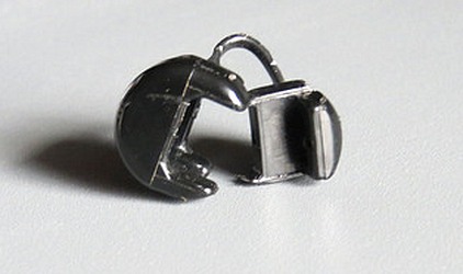
Why isn't the on/off switch on the
hot side? I believe it's because if the
non-polarized plug is plugged in backwards, and the
switch is on the "hot" side, Switch K, a
lug on each coil, and the stators of the
variable capacitors will have a direct connection to the
hot side of the AC outlet even if the set
is off. Like
this.
Since the cabinet was sold separately, some KT-135s
never had one. If a rotor plate on the variable
capacitor was bent and shorted, the whole chassis
would be hot. This sounds a
little far-fetched, but it's the only thing I can
think of. In any case, it's probably not a good idea
to switch the wires to make the radio "safer." |
|
|
|
|
|
|
|
|
|
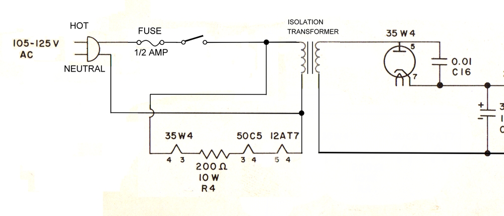
Lawr Salo modified his
KT-135 this way to isolate the radio from the
electric mains. Since the condition of the radio was
poor he had no qualms about drilling some holes in
the chassis and adding the isolation transformer.
"Hot" and "Neutral" are shown in case you're using a
polarized plug, otherwise it makes no difference.
You can also use a cord with a grounded plug, and
ground the chassis if using the transformer. Without
the transformer, grounding the chassis is an
extremely bad idea.
|
|
|
|
|
|
|
|
|
|
|
|
|
|
|
|
|
| Katie Wasserman's parents
threw her KT-135 in the trash while she was away at college. According to Katie,
the trash can was the near certain fate of 99% of
them. A guy named Karl Keller had one that was
burned up in a house fire. How many are left out
there? |
|
|
|
Note: Under cover of darkness, I carefully
packaged Art's radio and sent it to Karl Keller. I
told Art I'd give his radio a good home, and I did. |
|
|
|
|
|
| |
|
|
|
|
| |