|
Mike Peebles'
Two Tube Regen Kit mashup |
 |
|
|
| |
|
|
|
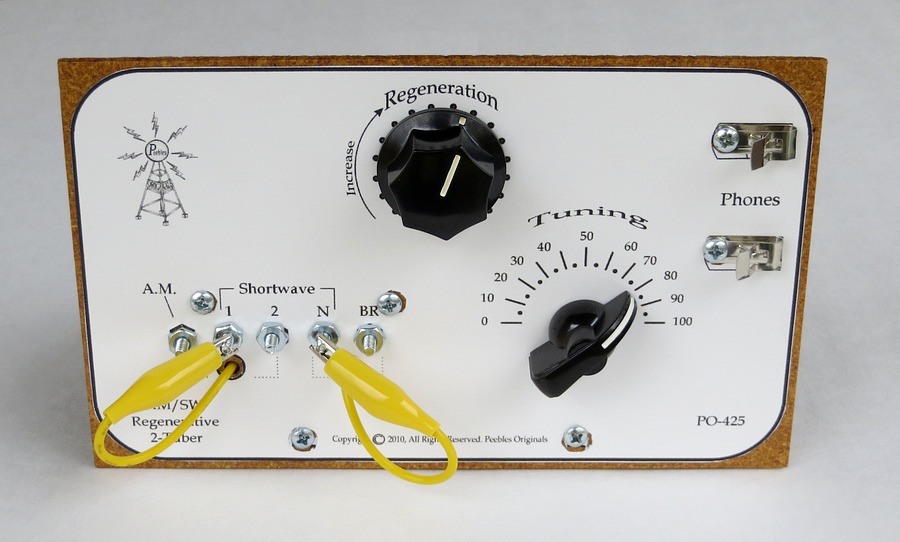
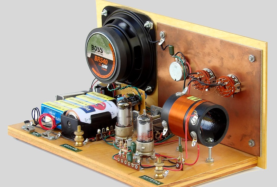
A Mike Peebles "PO-425" two tube regen
radio kit. |
| |
|
|
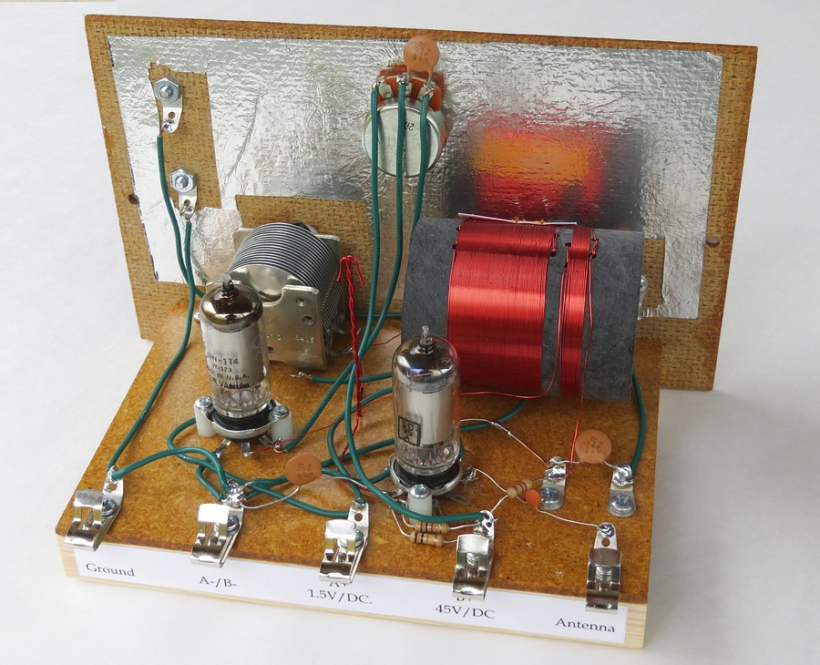
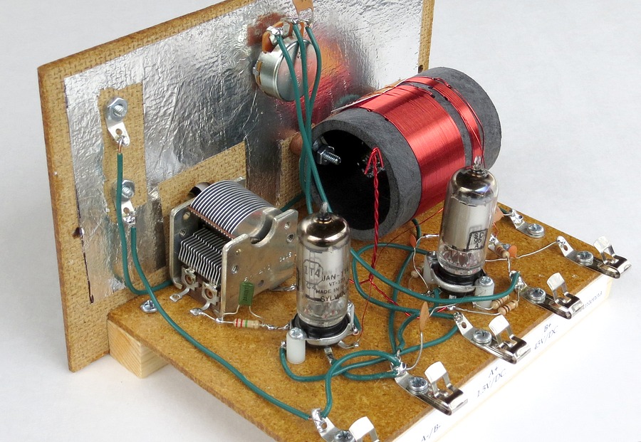
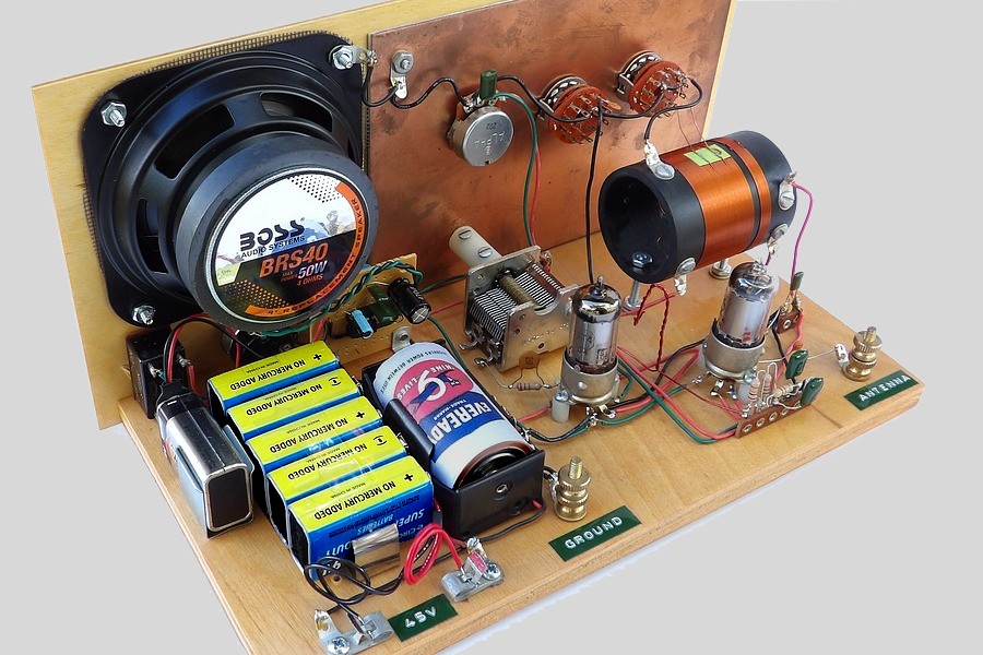
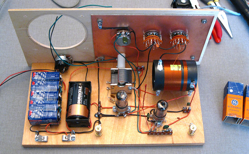
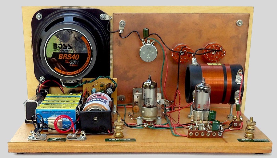
| Rear view of the assembled kit. |
| |
|
|
| A set of high impedance headphone
or an external amplifier are required to use this set. |
| |
|
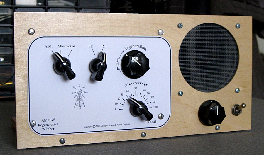
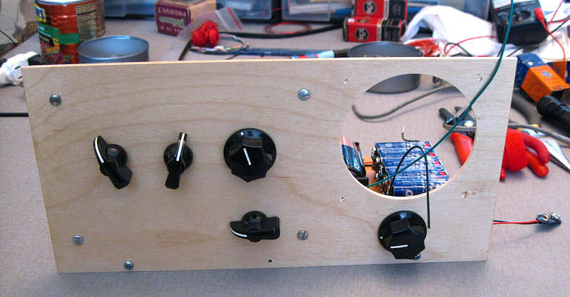
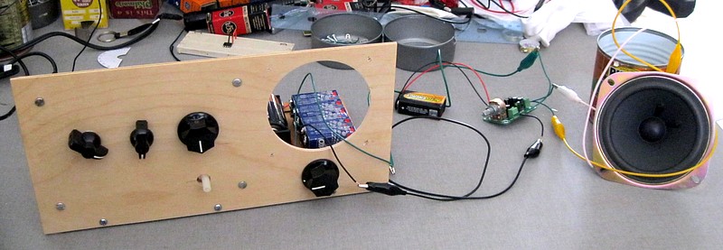
The same Peebles "PO-425" kit with added audio amplifier and speaker.
No headphones required. |
| |
|
|
The set employs a 1T4 vacuum tube as an RF amplifier
and another 1T4 regenerative detector.
|
| |
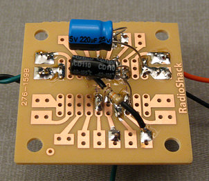
The audio output is fed to an LM386 audio amplifier IC mounted on a
board beneath the speaker.
|
|
| CONSTRUCTION |
|
|
|
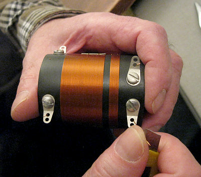
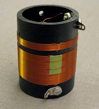
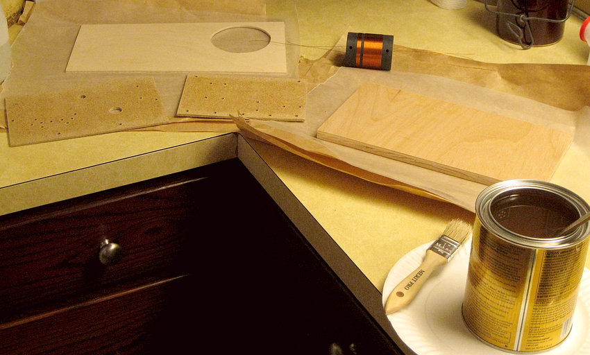
The first thing made was the coil. Sort
of.
Read more about the coil on the next page. |
The coil form is made of black PVC pipe and
came with
the kit. All the holes were pre-drilled by Mike Peebles. |
|
|
|
| |
|
Polyurethane on the kitchen counter (at two
in the morning) is easilly wiped up, but I tried to be neat. |
| |
|
|
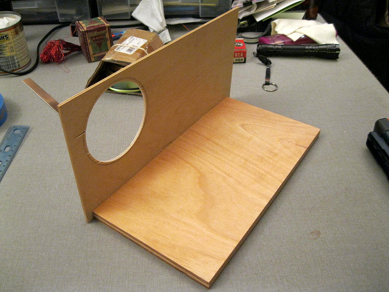
Andrea cut the base from 1/2 inch plywood. The front
panel is a thin sheet of plywood purchased at a craft store. The size of the front panel determined the size
of the base.
|
|
|
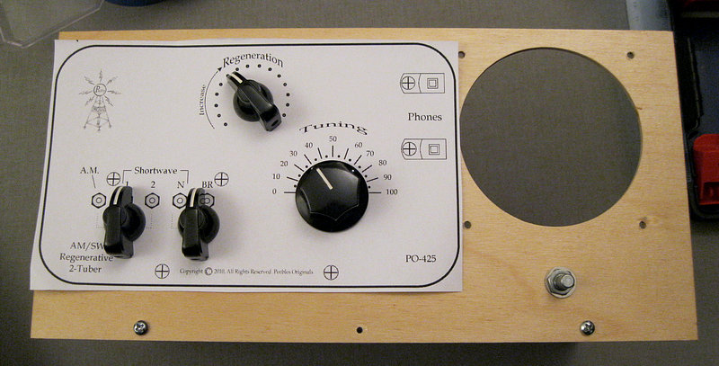
A test fit of the dial plate. Compare to the top
picture. The dial plate was edited to accommodate the rotary switches. |
| |
|
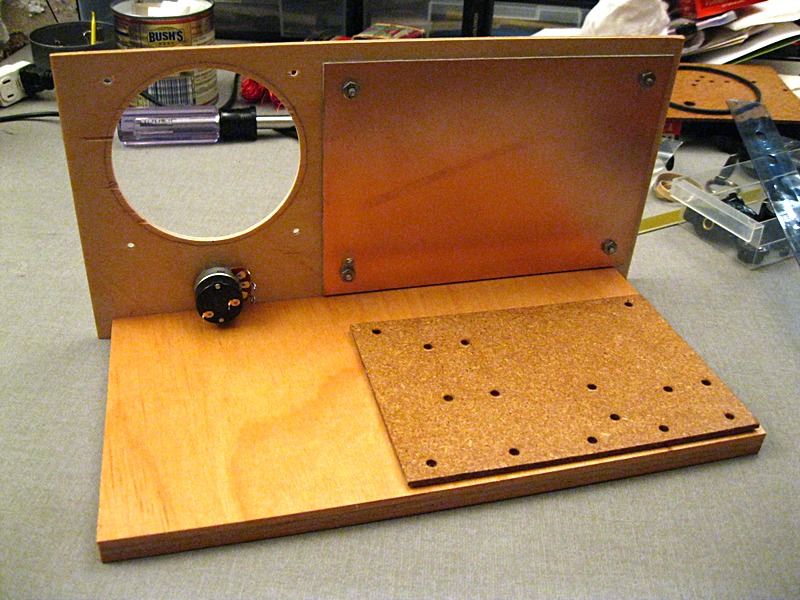
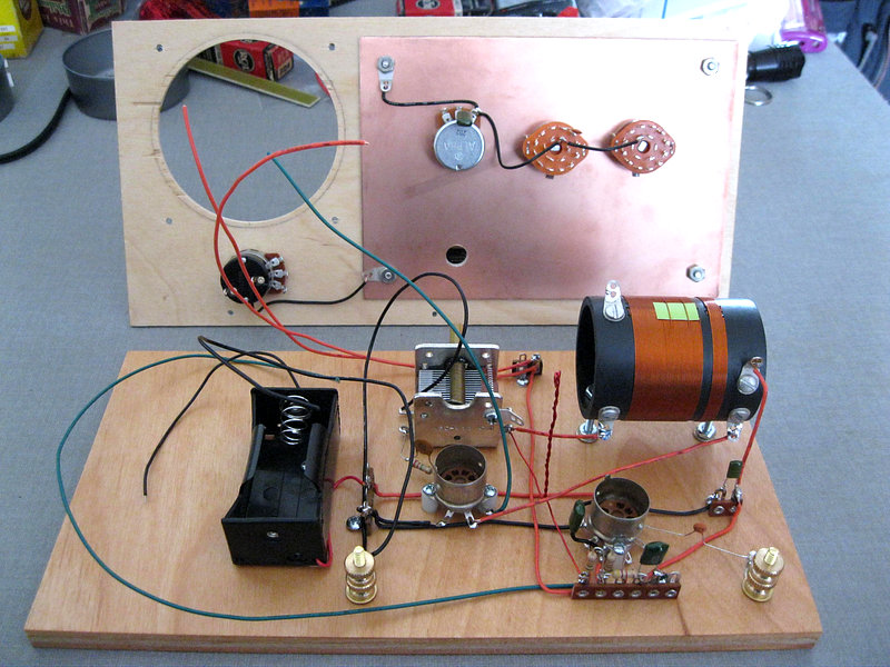
Next a copper plate was attached to the front panel
and the base from the kit was used to transfer the drilling spots. |
| |
All of the parts from the kit are mounted. Once the
front panel is attached and the coil is wired to the rotary
switch there
would be no way to remove the front panel. It had to be wired
correctly the first time. |
| |
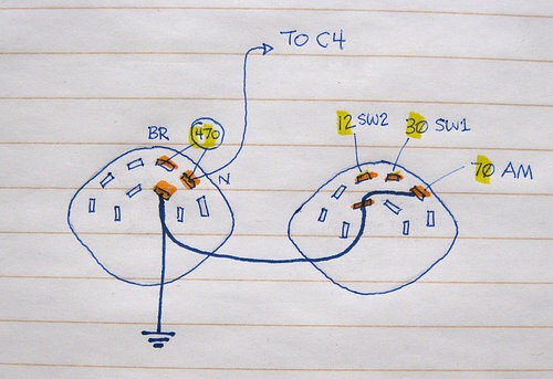
Because I'm easily confused (except when I
vote) I drew
a diagram of how the rotary switches should be wired. |
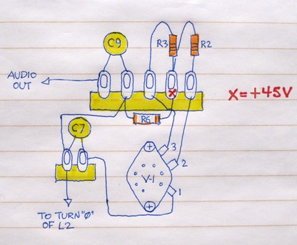
I also drew a diagram of how to wire the components,
since I had done away with two terminals in the kit. |
|
| |
|
|
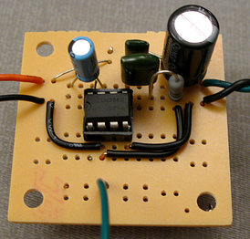
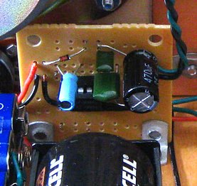
| Next the audio amplifier was
built. By the time all the batteries were in place there was almost no
room for it! This is a typical LM386 amplifier circuit. To add it you
just take the wires that would have gone to the headphones and
use them for the input to the amplifier. |
|
| |
|
At this stage the radio is working. The "kit" is
complete; all that is needed are the amplifier and speaker. |
| |
|
The radio can be tested by connecting high impedance
headphones to the two wires coming out of the speaker hole. |
| |
|
|
| Here it is connected to a small
amplifier and speaker for additional testing. |
| |
|
Completed on March 2, 2014. It looks kind of
"Steampunked". |
| |
|
|
|
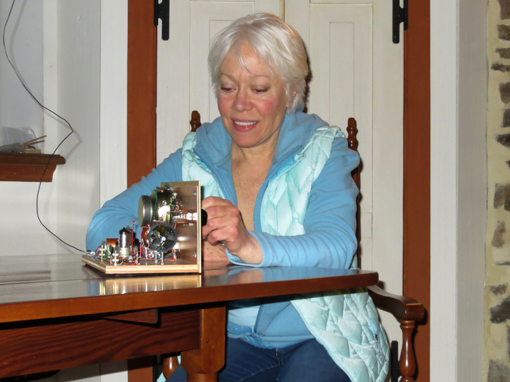
Andrea |
at the controls. We brought
the radio into the dining room because there would be less crap
in the |
| background for the picture.
With six feet of antenna wire and no ground we picked up several
locals. Regeneration |
| on the BCB is very smooth. It's much tighter on the Shortwave settings. |
| |
| Over a dozen Shortwave
stations were easily heard the first time the set was tested, as
well as several "hams". |
|
The set tunes to about 6200 kHz. In addition, the "Shortwave
1" setting spreads out the top of the broadcast |
|
band nicely. |
|
|
|
One word of caution - with the added amplifier turned up the set
picks up EVERYTHING that emits interference. A strong
signal, however, easily drowns out the interference. Some of the
shortwave stations were very loud and clear. (This was about an
hour after sunset). Televisions,
computers and light dimmers will cause a buzzing in the radio. |
|
We just turn off the protected outlet strips
that everything is plugged into and the airwaves become quiet.
|
|
|
|
|
|
|
| |
| |