 |
The
OZARK PATROL |
 |
|
|
|
|
|
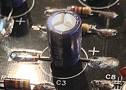
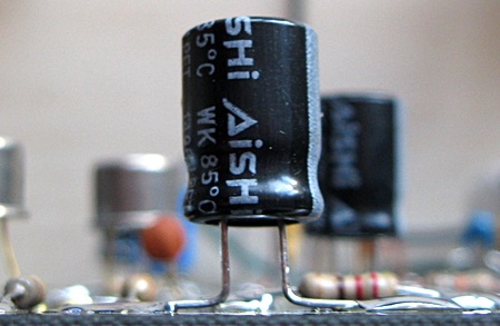
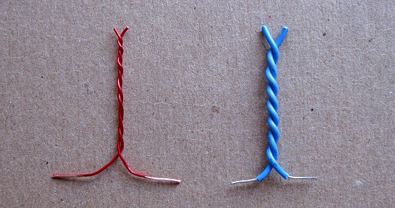
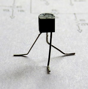
The picture on the left, from the 4 State website,
shows the method of bending the component leads.
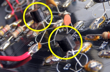
I chose to make the leads longer to avoid any damage from the
soldering iron, especially to the transistors. |
|
|
|
|
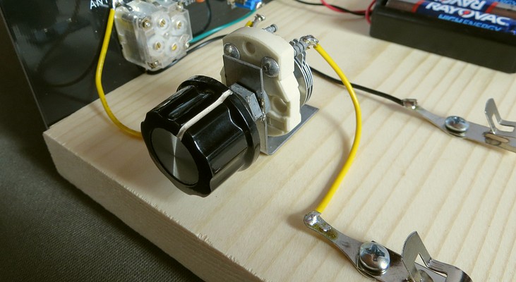
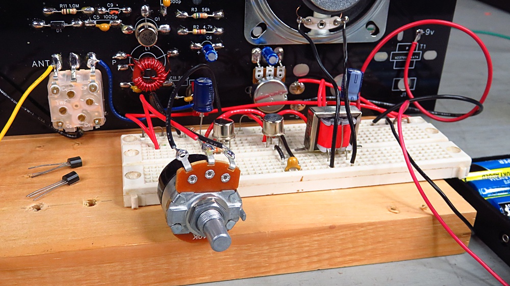
This is a capacitor added to tune the
antenna. It doesn't come with the kit. To couple the antenna
to the radio, a very low value capacitor is used. It's made
by twisting two pieces of wire together and is called a
"gimmick." A gimmick capacitor has a value of about 1
picofarad per inch, depending on how tightly the wire is
twisted. I wanted to be able to vary the capacitance. |
|
| |
|
|
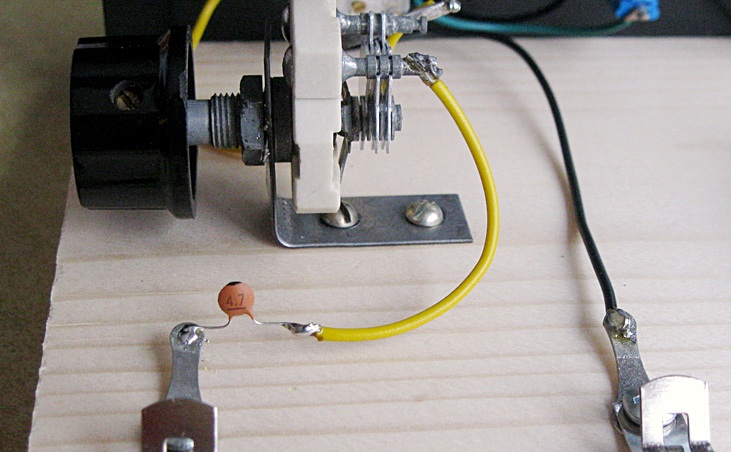
The capacitor used
was 0 to 28 pF, which is too high. I could only mesh the plates a tiny
amount and then it was too much.
I put a 4.7 picofarad capacitor in series with the variable. What do
you suppose that did to the value of the variable capacitor?
|
To calculate the value
of two capacitors in series, the formula is C1 x
C2 / C1 + C2.
So (28 times 4.7) divided by (28 plus 4.7) =
131.6 divided by 32.7
(I used a calculator) = 4.02. The variable capacitor is
now 0 to 4 pF!
It is perfect for this. You don't really
need it if you're building the kit; the gimmick will work
fine. I just happened to have the variable capacitor
available, so I used it. |
|
|
|
Gimmick capacitors. You'll put your eye out with
those things! |
|
|
|
|
|
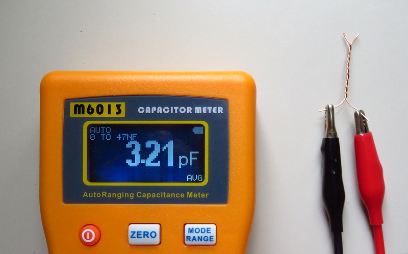
Value of a typical gimmick capacitor. |
|
|
|
|
|
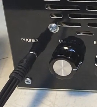
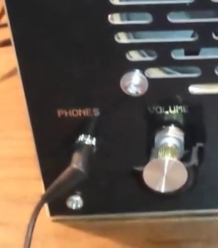
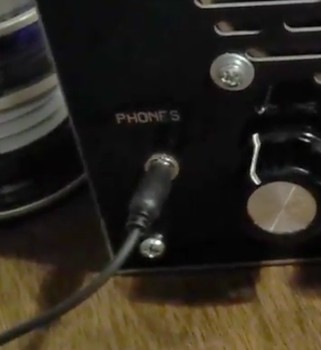
The audio output of the radio is
disappointing. The volume is so low It was actually in
competition with the noise from our refrigerator while
listening to it. Then I plugged in a pair of headphones and
the difference was amazing.
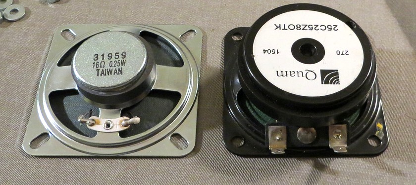
The speaker was replaced. It improved the sound, but not the
volume.
Once you listen to the radio with headphones you probably
won't use the speaker. The volume in the
headphones is so loud that you'll have the sound turned almost all the
way down. |
|
| |
|
|
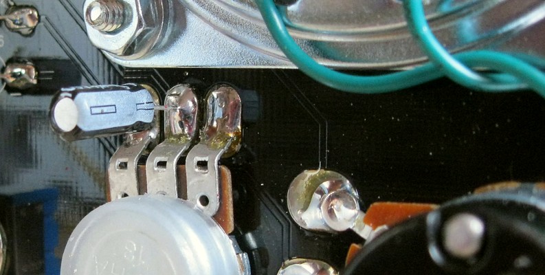
| The speaker frame is
very close to the terminals on the regen control, so be careful when
attaching it. |
|
|
|
In another effort to get more volume,
I replaced the 2N3019 transistors with some 2SC458s that I
had left over from the Astro Commander walkie-talkies (seen
elsewhere on this site). I don't think it made a difference.
The level of sound from the speaker was still abysmal, and
It wrecked the cool look of those silver and brass metal
2N3019s.
The reason I used the 2SC458s was because they worked so
well in the walkie talkies. I knew they were good to at
least 27 megahertz (way more than what was needed here)
and the walkie talkies have plenty of volume.
The "Pittsburg style"
construction lets you swap out a transistor in less than a
minute. This came in handy when comparing the performance,
since listening conditions on the short wave bands can
change from minute to minute. |
|
|
|
|
|
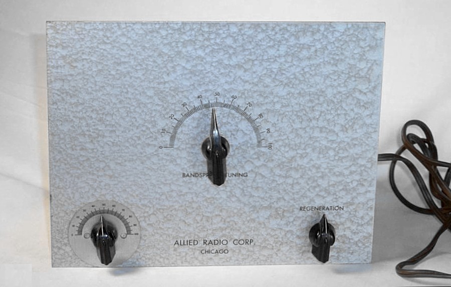
The 4 State
QRP Group considers the "Ocean Hopper" an ancestor of the
Ozark Patrol. The Ocean Hopper DIDN'T HAVE A SPEAKER.
Perhaps instead of trying to improve the dismal volume of the
speaker in the Ozark Patrol, just ignore the fact
that it even has one.
|
|
|
|
| If the Ozark Patrol was
made without a speaker, it would be cheaper, and nobody
would get the impression the radio doesn't work very well,
because it DOES work very well if you use headphones. A cool
"4 State QRP Group" decal could be placed where the
speaker used to be. |
|
|
|
|
 ...and
then I had an idea.
 |
|
|
|
While watching some YouTube videos of
other Ozark Patrols, I got an idea. Yes, another one.
That's a total of FIVE, no, THREE ideas! The videos show an
external amplified speaker plugged into the headphone jack.
So why not make the amplifier on-board? Literally on the
board.
|
|
|
|
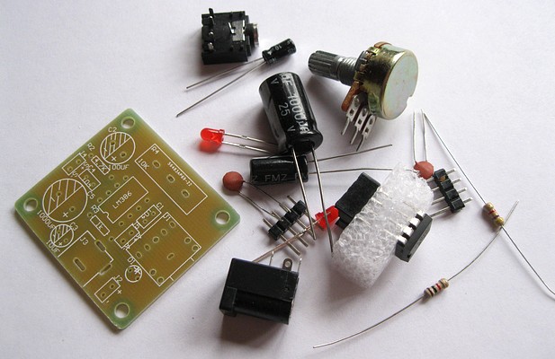
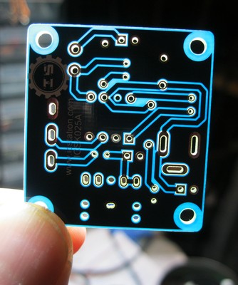
For a buck you can get this amplifier kit from
China on ebay. No postage! I ordered three. I mean, five.
The soldering pads are very small, so there is a learning curve
after flowing all that solder onto the Ozark Patrol. |
|
|
|
|
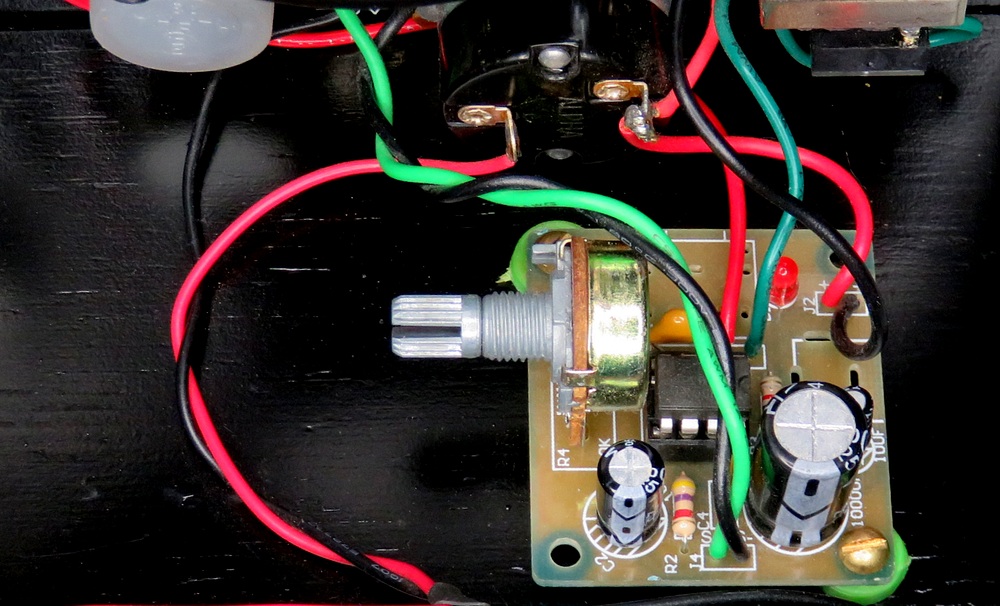
| The little amplifier
is mounted behind the volume control. "Set it and forget
it." |
|
|
|
|
|
THREE WAYS TO CONNECT THE AMPLIFIER |
|
|
|
| To install the amplifier you first
disconnect the speaker. The input to the amplifier are the
wires that formerly went to the speaker. The leads from the amplifier output then go to the speaker.
Power comes from the on / off switch on the front panel. Set
the volume on the amp to where you want it, then forget it.
You still control the volume from the front panel, but now
you have some SERIOUS volume. |
|
|
|
|
|
|
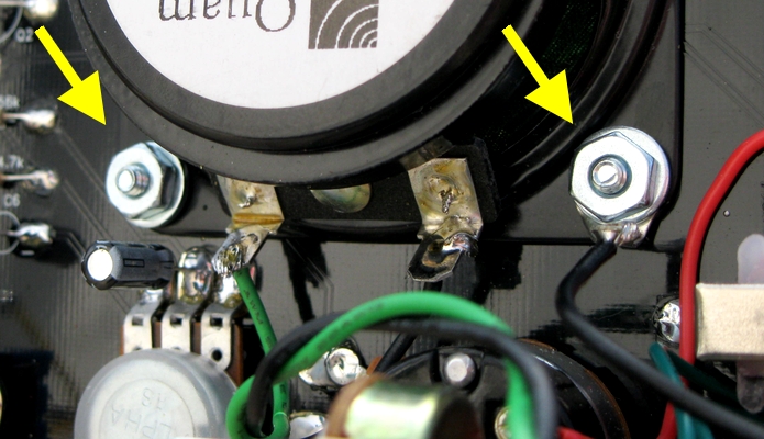
You can pick up a ground for the
amplifier from any of the screws that mount the speaker. You can
also use the B- from the battery. The 9V+
comes from the On/Off switch.
|
|
|
|
|
|
|
|
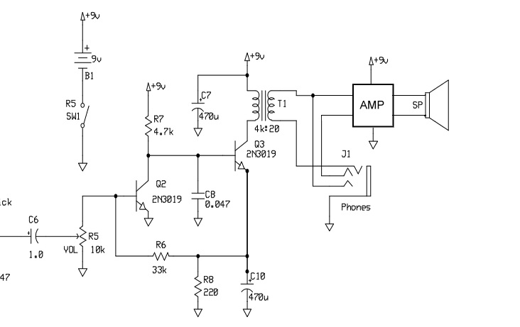
Partial schematic with LM386 amplifier |
| Connecting the input of the the amplifier
directly to the transformer (in place of the speaker) gives the radio a
tremendous increase in volume. It can be ear splitting.
There is a 10 mfd capacitor on the LM386 module across pins
1 and 8 that controls the gain. You can remove it if you use
this configuration.. |
|
|
|
|
|
|
|
|
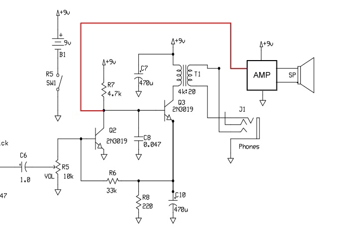
| By bypassing the last transistor and
the transformer, the sound is clearer and the range of the
volume control is better, though it isn't nearly as loud. This is very easy to do, all you
need is a wire from the collector of transistor Q2 to the
amplifier. |
|
|
|
|
|
|
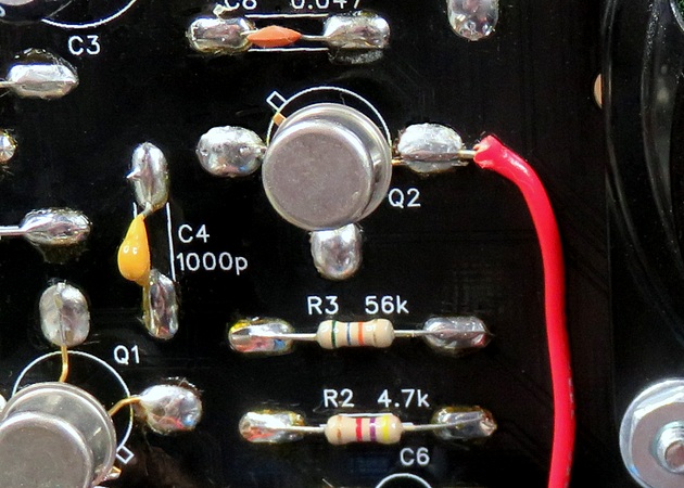
Here's the wire attached to the collector Q2,
which goes to the input of the amplifier. |
NOTE: Connecting the amplifier this way will NOT
cut off the speaker when the headphones are plugged in.
To turn
off the speaker, turn down the volume all the way on the
little amplifier. |
|
|
|
|
|
|
|
|
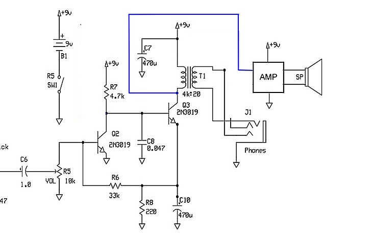
| A third way to connect the amplifier
is to take the output from the collector of Q3. If you use
this configuration, remove the 10 mfd gain control capacitor
from the LM386 module. |
|
|
|
|
|
|
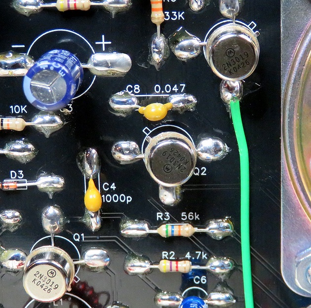
Here's the wire attached to the collector Q3,
going to the input of the amplifier. |
|
|
|
|
|
|
|
|
Which way works better? They each have their
advantages. Click on the picture to see a video of some tests. |
|
|
|
|
|


