|
|
|
|
|
|
ANOTHER MRL No. 2? |
|
| |
|
|
|
| |
|
|
|
| |
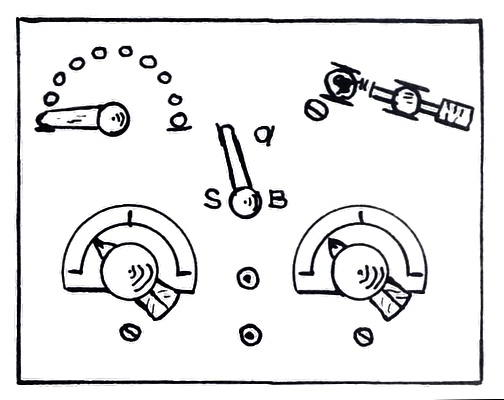
MRL No. 2 |
Morgan crystal set
Page 92 |
|
| |
|
|
|
|
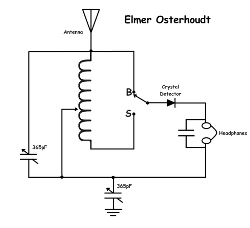
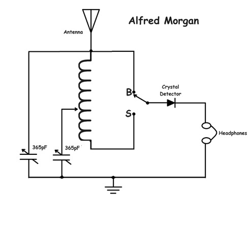
| There seems to be
a clone of the No. 2 Crystal set in the book "FIRST RADIO
BOOK FOR BOYS" by Alfred P. Morgan,
Copyright 1941.
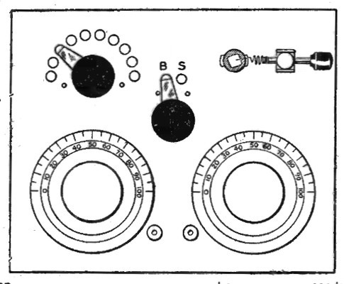
The picture from Morgan's book is on the right. Alfred P.
Morgan wrote over 15 books on radio. Would he copy Elmer's
circuit into one of his own books? |
|
|
|
|
|
|
They certainly look similar. Which circuit works
better? I tried both, and the Morgan circuit
doesn't work at all. The problem is the variable capacitor in series
with the coil tap selector. A guy named Hue Miller emailed that there is a mistake in the Alfred P. Morgan circuit. |
|
|
|
|
|
|
|
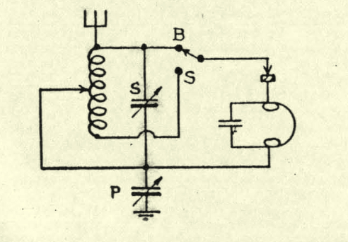
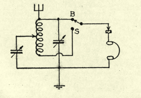
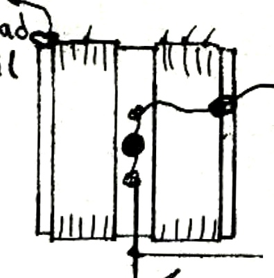
The schematics redrawn by Vic Rodriguez. Hue Miller stated that the
Morgan circuit would work if the crystal was placed across the
headphones. |
|
|
|
|
|
|
|
|
|
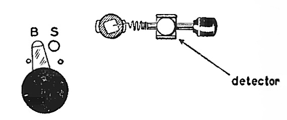
A crop from the picture in the Alfred Morgan book. All modern AM radios need a "BS" detector and switch!
The term "BS" or "Bullsh*t" didn't become popular till after WWII.
Morgan's book is copyright 1941.
|
|
|
|
|
|
|
|
|
|
|
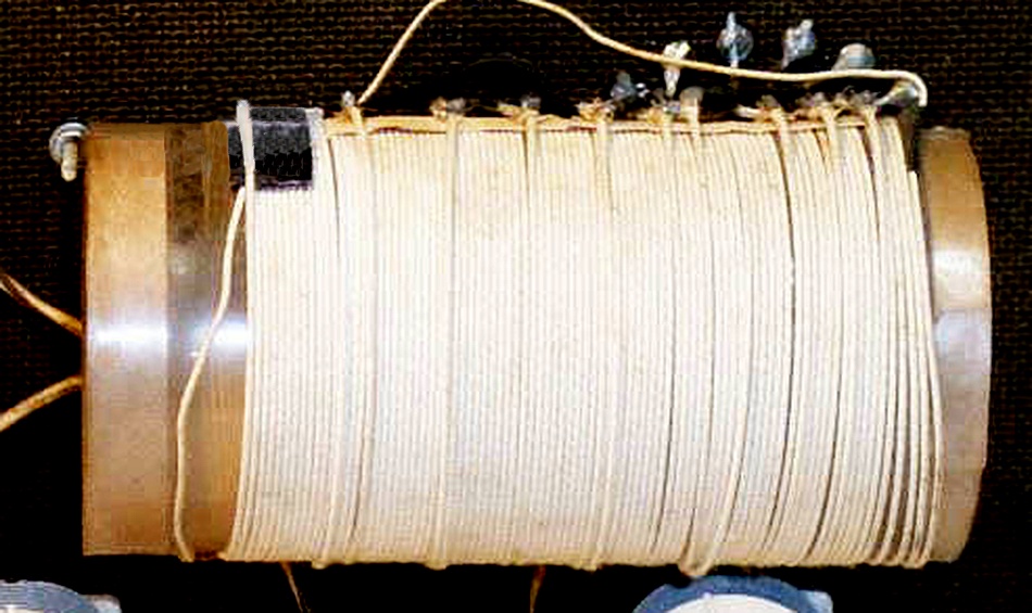
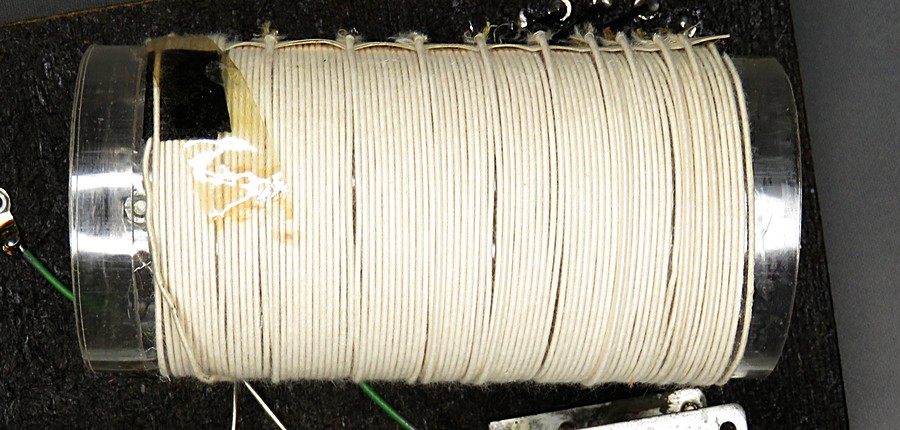
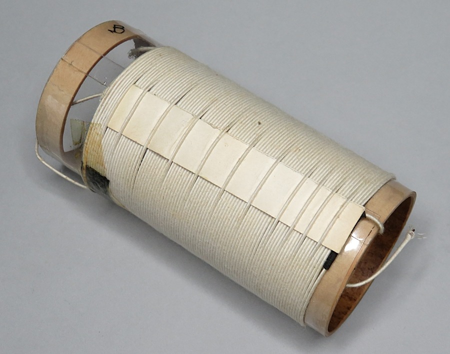
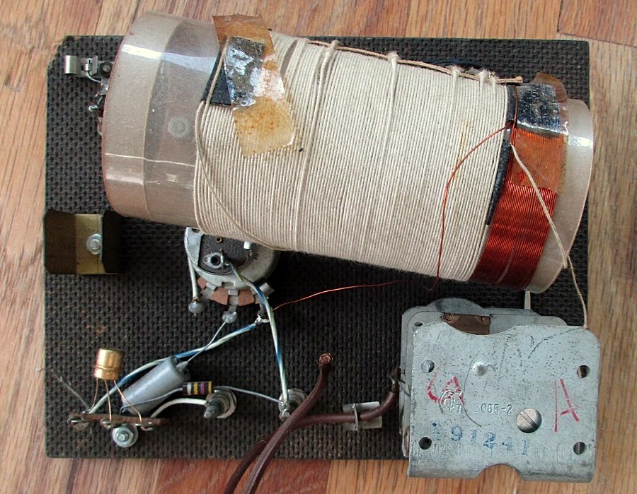
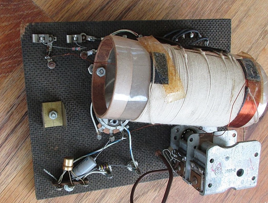
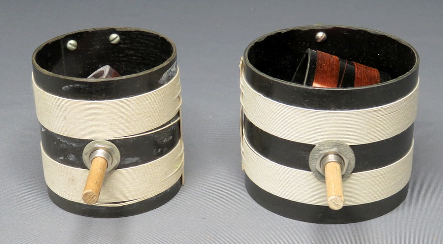
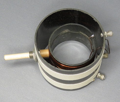
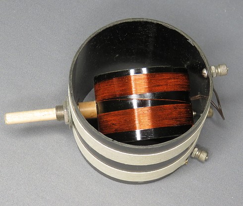
| Here are two examples of the MRL No. 2
coil. The one with the fiber rings at the ends is the
oldest, but they both show signs of the celluloid shrinking
from age. |
|
|
|
|
|
|
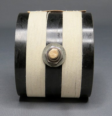
An unused No. 2 coil from the 1980s. |
|
|
The coil form is 2" in diameter by 4.5"
long. The coil is 90 turns of #22 cotton covered wire,
tapped at turns 5, 10, 16, 23, 40, 50, 61 and 73.
What formula did Elmer use to determine the taps? Did he
calculate the inductance of each tap and determine the
frequency the coil will resonate at depending on the
position of the variable capacitor? |
|
|
|
|
|
|
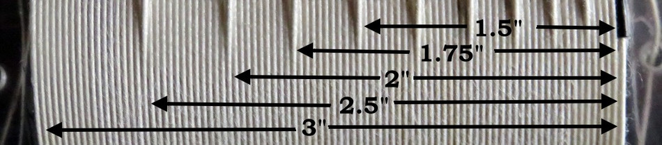
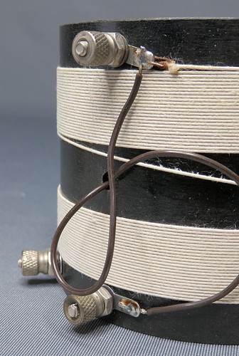
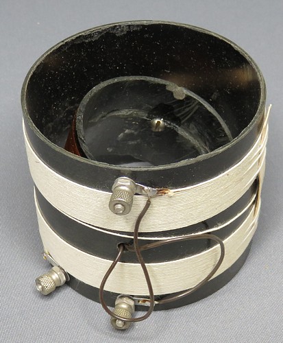
It seems he used a ruler! The coil is tapped
at 1/4, 1/2, 5/8, 3/4, 1½,
1¾,
2, and 2½
inches. |
|
|
|
|
Another MRL Advertisement |
|
|
|
|
| |
|
|
| In November of
1958, "Electronics Illustrated" magazine announced
they were accepting classified ads. This MRL
advertisement appeared in the very next issue. |
|
|
|
|
|
|
|
|
|
|
|
|
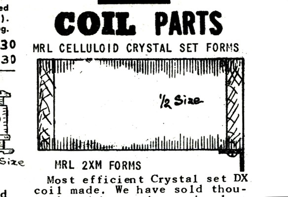
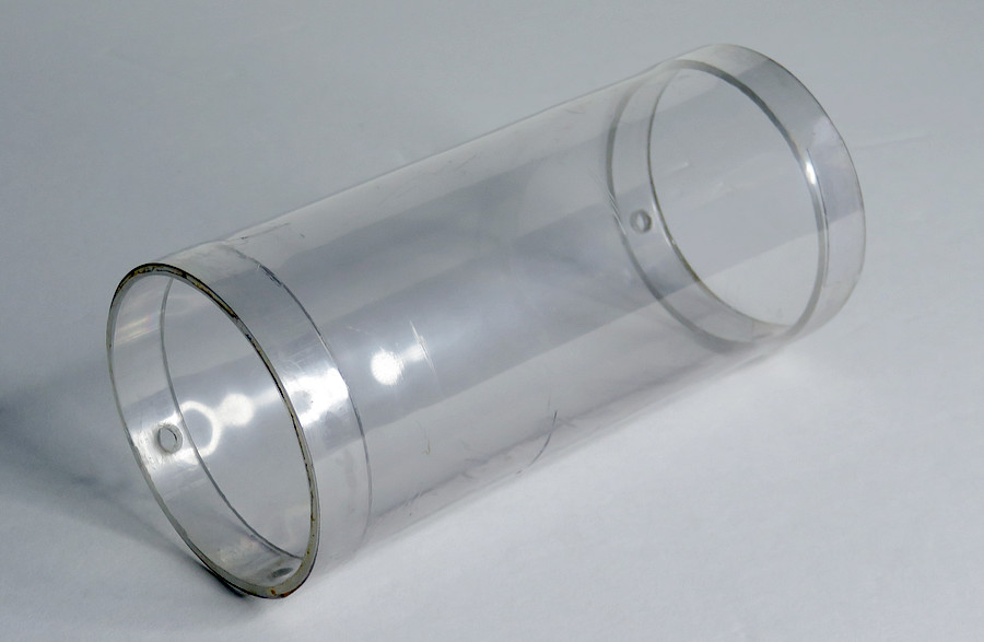
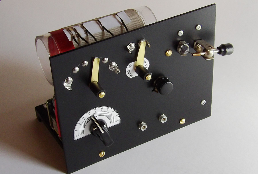
If you saw this in the catalog, what do you think it
would actually look like? |
|
|
|
|
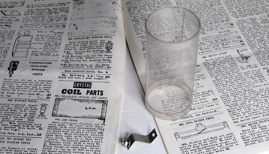
It's a beautiful, hand-made, low loss, high-Q,
transparent celluloid coil form. 2" in diameter x 4.5" long.
According to an advertisement in Radio magazine, the first 2"
celluloid coil forms were sold in July of 1934. |
|
|
|
|
| The 2XM coil form is the
heart of many of the crystal set kits and plans in Elmer's
literature. The cost in 1972 was 45¢.
In 1985 it was a dollar. An MRL-made mounting bracket
was included. This bracket was not sold separately in the
catalog. |
|
|
|
|
|
MRL No. 26
Diode-Transistor All Wave Set |
|
|
|
|
|
|
|
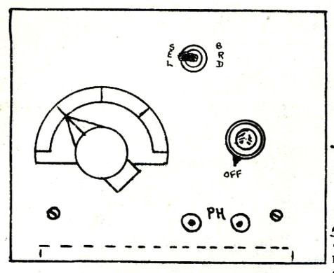
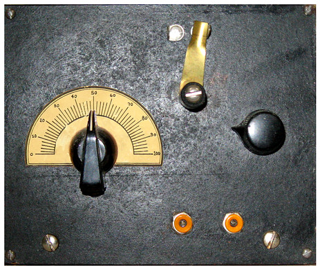
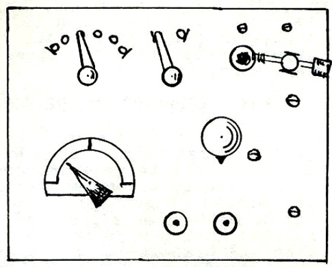
Catalog entry for the No. 26 and an actual No. 26
built in 1978 by Sloane Freeman. |
|
|
|
|
|
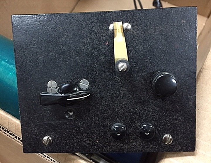
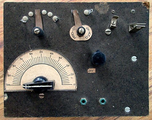
Another MRL No. 26, this one built by Don Holdaway.
That brass switch looks new! |
|
|
|
|
MRL No. 10
All-wave Diode-Transistor Set |
|
|
|
|
| |
|
|
|
|
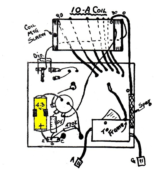
Catalog drawing for the #10 and an actual #10 built
over 50 years ago.
The kit came with all the parts, a 4.3 volt battery and a
copy of DP-34. It sold for $8.50. |
| |
|
|
Rear view of
the MRL Number 10 shown above. This was built in 1971.
On the left is the battery holder, but the battery and
connecting wires are missing. |
| |
|
|
| Notice the 2
gang variable capacitor. |
| |
|
|
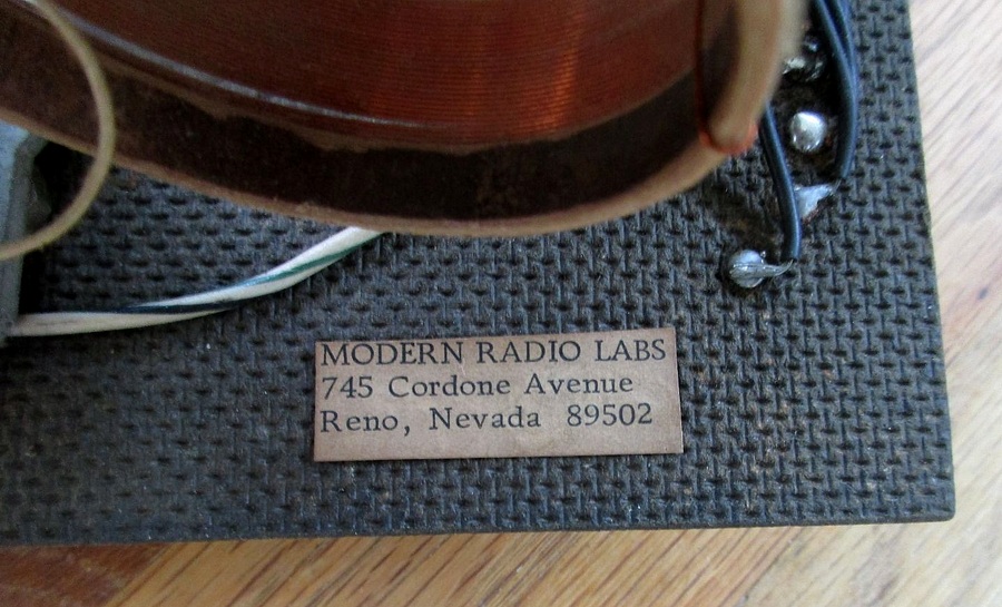
| This address
dates the radio to 1971 - 1972 |
| |
|
|
| Reproduction
made in 2022. |
| |
|
|
|
The 4.3 volt Mercury battery is so
rare I can't find a picture of one.
According to the catalog, the battery holder will
fit an AA or a 4.3V mercury.
MRL trivia: Elmer sold Burgess batteries because you
could solder to the negative side, unlike other
brands. |
| |
|
|
|
|
MRL VARIOMETER |
|
|
|
|
|
|
|
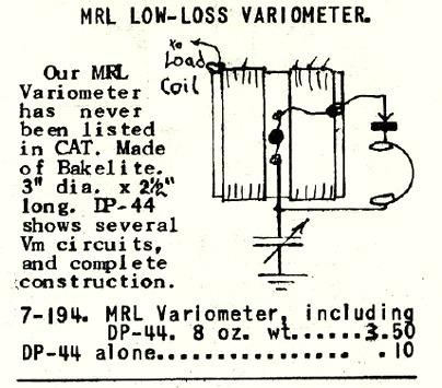
Here's another
drawing that is ambiguous, as is the statement "has never
been listed in CAT." How can it not be listed in the catalog
if you're looking at it in the catalog? Obviously, it was
only intended for the first catalog to list the variometer
but the line stayed in for all the other catalogs.
What is it? What does it look like in real life?
|
|
|
|
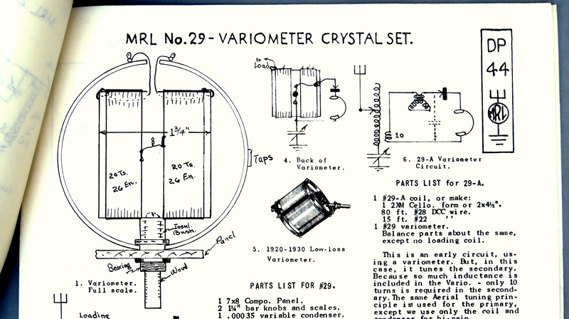
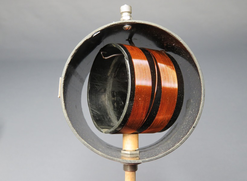
| The
catalog hints we should get DP-44. Here is the
variometer in DP-44, drawn actual size in the
publication. Unfortunately, Elmer's drawing shows it
as viewed perfectly down from the top. It looks like
two rectangles in a square inside a circle. |
|
|
|
|
|
|
|
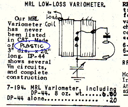
The square and the circle are cylinders! |
|
|
|
|
The rectangles are coils! The black dot in
the center is a control shaft.
|
|
|
|
Two different sizes. |
|
|
|
|
The coupling between the coils is varied by
turning the inside coil.
|
|
|
|
|
Another MRL masterpiece! How many of these
would he have sold if he had put a picture of one in the
catalog? If you scroll back up and look at DP-44 again,
you'll see he has a picture of a "1920 - 1930 Low - Loss
Variometer" next to his drawing. Why didn't he use a photo
of his own variometer?? |
|
|
|
|
|
|
This one was obtained by Vic Rodriguez in
2024 from ebay. |
|
|
|
|
MRL TRANSISTOR AMPLIFIER |
|
|
|
|
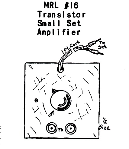
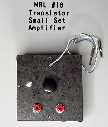
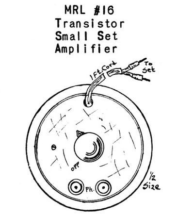
MRL No.16 amplifier drawing and actual item. |
|
|
|
|
|
Radio Builder and Hobbyist No. 48 states the
amplifier
became available on May 1, 1959, but in a round plastic box. |
|
|
|
|
|
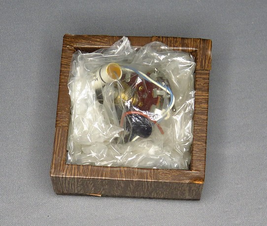
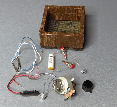
This is an unassembled kit from 1986. If you
purchased it already wired, a 9 volt battery was included. |
|
|
|
|
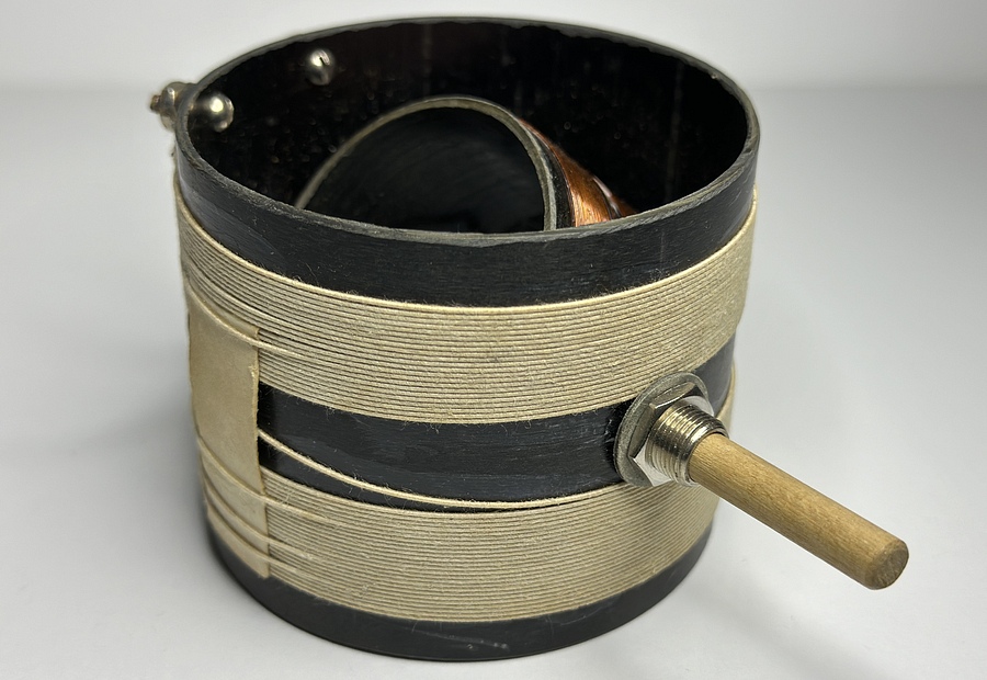
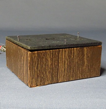
The most interesting aspect of
the kit is the box! Elmer made a wooden box, then
covered it with wood grain Contact Paper. How long
did that take? Why didn't he stain or paint it
instead of covering it?
|
|
|
|
|
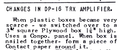
An explanation of the box, from MRL Data
Sheets Vol. 6 |
|
|
|
| |
|
|
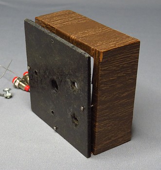
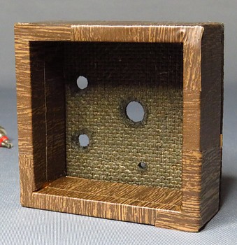
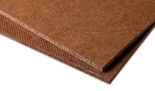
Look at the underside of the front panel
in the middle picture. We've just solved the mystery of what
Elmer calls "Compo." It's Masonite!
Note: In HB-5, Crystal Set Construction, page
3, Elmer stated that "Compo." is Masonite. However, HB-5
wasn't published till 1956 and he had been calling it
"Compo." for two decades prior. |
|
| |
|
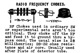
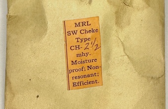
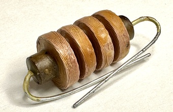
| MRL RF CHOKE |
|
| |
|
|
|
|
|
Catalog picture. |
Envelope from MRL. |
Choke contained in envelope. |
|
| |
|
| |
|
|
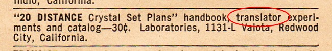
| Misprint in the February 1959
edition of Popular Electronics. Fortunately it only ran for
one month. |
|
| |
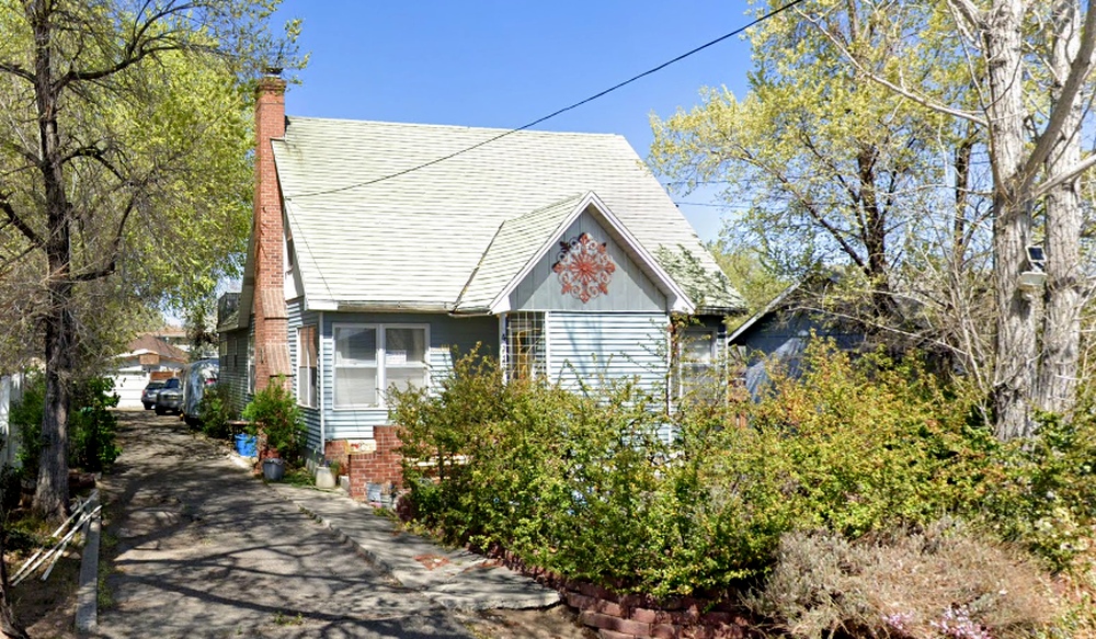
| MOVING MRL TO RENO, NEVADA.
TWICE. |
| |
|
|
| In 1951 Elmer and Mabel moved 250 miles
from San Carlos California to this house at 411 Capitol Hill
Avenue in Reno, Nevada. The house was built in 1941. A year
later they moved to Redwood City, California. San Carlos and
Redwood City are only 2.5 miles apart. |
|
| |
|
|
|
|
|
|
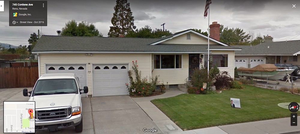
In 1971 Elmer
and Mabel moved from
Sacramento,
California to this house in Reno, Nevada. Why would
they move to
Reno, Nevada? Twice. In 1984 Elmer wrote that years
previous Mabel would sometimes go to Reno for a
week. During that week he'd go into the shop at 6AM
and write a handbook. Apparently there was something
about Reno that appealed to Mabel. Elmer said they
didn't gamble, that was for the tourists.
A year
later they moved to Garden Grove, California.
It was only a two hour drive from Sacramento to Reno
in 1971, but the trip from
Reno to Garden Grove is over 500 miles and would
have taken all day. Every time they moved, they
moved seven and a half tons of MRL with them. |
|
|
| |
|
|
| |