|
1947 Motorola Model 67-X |
 |
|
|
|
|
|
|
|
|
|
|
|
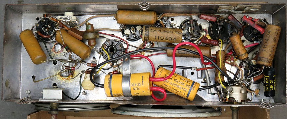
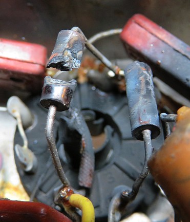
Inspection of the chassis. The first thing we
see, at the bottom center of the photo, is a large capacitor
flopping around. IT HAS A METAL BRACKET ON IT! |
|
|
|
|
|
|
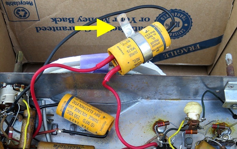
When the radio was
turned over, the metal bracket had wedged itself between two of the
pins on a tube socket, shorting them out. Apparently, a
previous "repairman" relied on GRAVITY to keep the bracket out of
the circuit. |
|
|
|
|
|
|
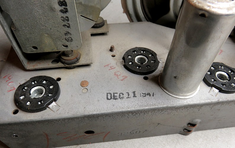
The date stamped on the radio. 1947 was the year
Galvin Manufacturing Corporation officially changed their name to
Motorola, Inc. The brand name "Motorola" had been around since 1930
when Paul and Joseph Galvin began manufacturing car radios. The car radio
had been invented by William Leer and Elmer Wavering, then perfected
by them and Paul in Galvin's shop.
The radio above was probably manufactured in Chicago, Illinois. (In
1948 Motorola moved to a 185,000 square foot manufacturing facility
in Quincy, Illinois.)
The set contained five Sylvania tubes and an RCA audio
output tube.
The Sylvania tubes tested good except for the 14B6 (Detector and
Automatic Volume Control). The RCA 35A5 audio amp couldn't be
tested. There was no listing on the tube tester. |
|
|
|
|
|
|
|
|
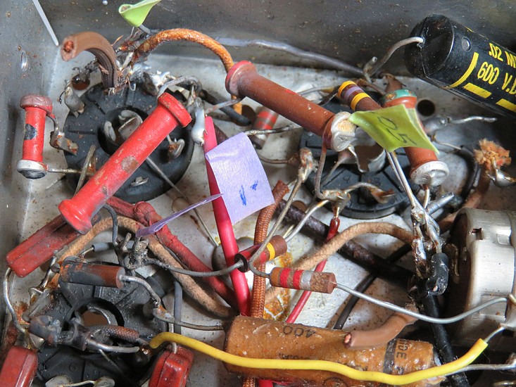
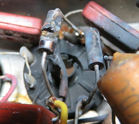
This radio was repaired in the past. From the
looks of the capacitors, it was a long time ago. It seems the
repairman didn't use any solder and just reheated whatever was
already there.
Two replacement capacitors are wax
coated Stromberg Carlsons; two are paper Stromberg Carlsons with
no wax. Two are wax coated made by Sprague and one is a plastic
Sprague. The craftsmanship (or lack of) shows that at least three
people worked on this, probably four, with the later addition of the
plastic Sprague capacitor.
Finally, there was the guy who replaced the AC cord and ruined the
radio. After working on this radio, I can say that the fact that he even tried to
replace the cord is a testament to his courage. |
|
|
|
|
|
|
|
|
|
"Solder? We don't need no steenking solder!" |
|
|
|
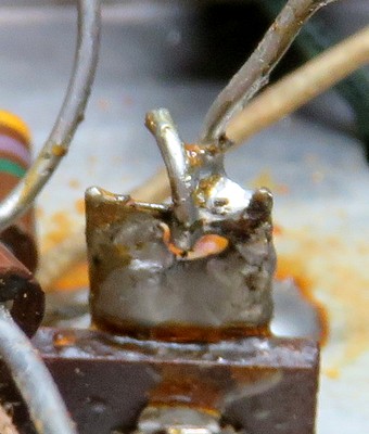
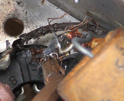
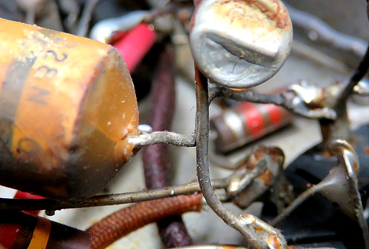
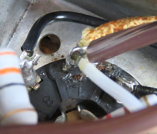
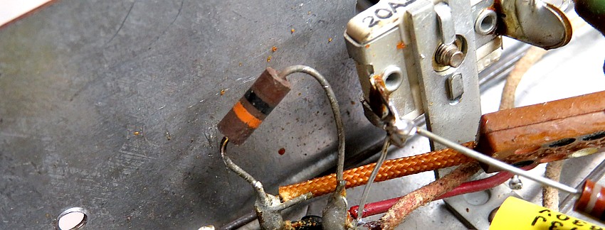
Here's the exploded
resistor and what I think caused it. On the right, a new
line cord has been soldered to pin 1 of the rectifier tube.
(The number 1 on the socket is upside down in the picture.)
Some strands of wire from the cord are touching the chassis.
|
|
|
|
|
|
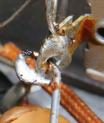
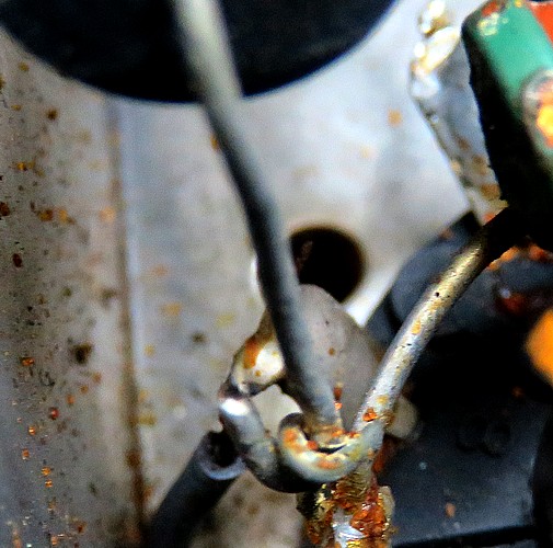
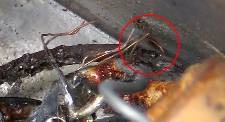
| This is as close as I
could get with the camera. There appears to be a burn mark
on the chassis where the wire is in contact with it. It was tested with an ohm meter
and it is a very good connection. Probably better than some
of the intended connections. |
|
|
|
|
|
|
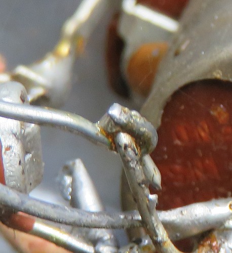
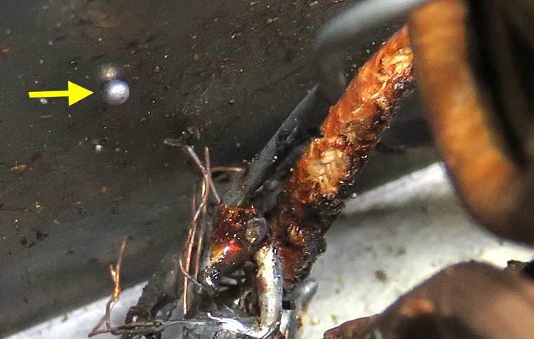
The small explosion flung a tiny molten ball of
solder against the chassis. |
|
|
|
|
So touching. This should be a Hallmark
card. |
|
|
|
|
|
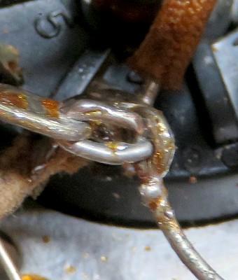
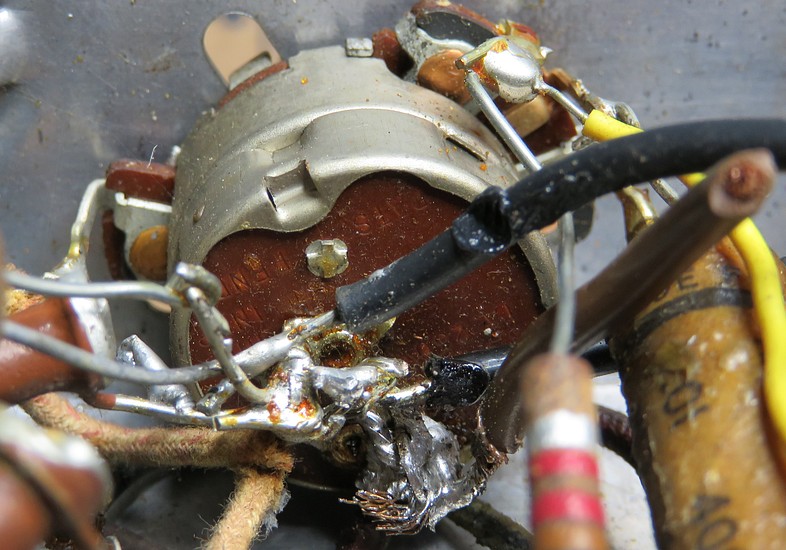
| When I viewed the
On/Off switch connections I was "stricken dumb with
astonishment and amazement which bordered on stupification." |
|
|
|
|
| Two capacitors have been
removed just to be able to see this mess. How do you get a soldering
iron in there? |
| |
|
|
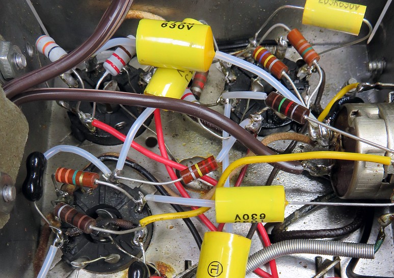
| Almost every component was replaced.
Teflon "spaghetti" insulates many of the leads, sometimes
needlessly. |
| |
|
|
|
|
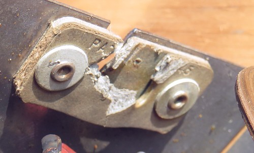
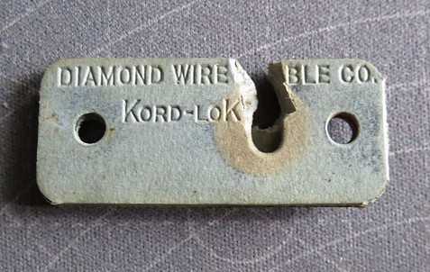
Apparently, the way to replace the AC
cord is to cut the connections to the radio, then destroy
the KORD-LOK
strain relief by digging the cord out with a screwdriver.
|
|
| |
|
|
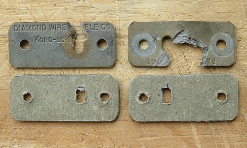
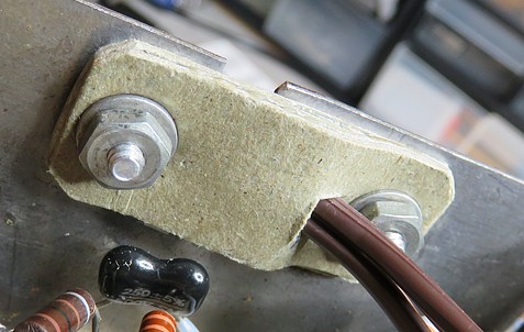
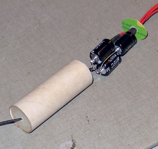
Crude replacements made
of cardboard and glue sandwiches, covered in
Polyurethane. They work as well as the real deal, the cord
is cinched down unbelievably tight but it's very gentle on
the cord.
I was going to use pop rivets
to hold them in place but reconsidered. The Motorola rivets
were probably used to keep the production costs down and the
repair costs up.
|
|
|
|
|
|
Revisiting the scene
of the crime. |
|
|
|
|
| The exploded resistor
has
been replaced. |
|
|
|
|
|
|
|
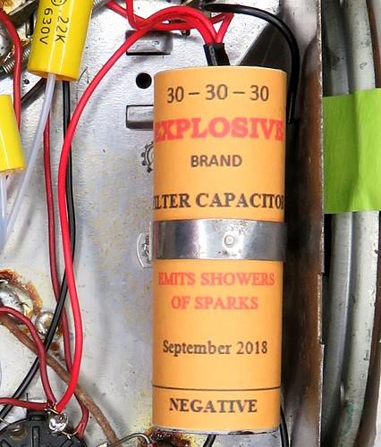
The new filter capacitor. The metal bracket from
the old one was used to hold it in place. "EMITS SHOWERS OF SPARKS." |
|
|
|
|
|
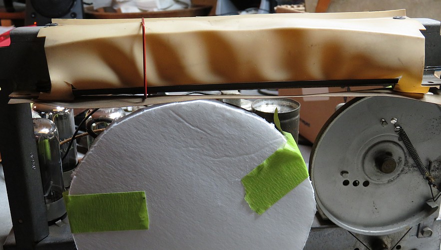
| Before we can turn the
radio on and try to tune in a station, we have to remedy
another problem. There is a piece of plastic that is
illuminated by the pilot light to make the dial face glow.
It has warped to the point where the dial pointer has to
bend as it is dragged across it. |
|
|
|
|
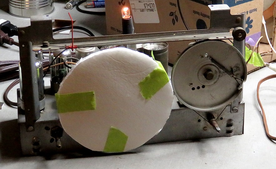
The plastic piece was
removed, and the radio was turned on. The pilot light, which
once worked, decided to burn out. It was replaced and the
radio was turned back on. The light came on but the radio
picked up nothing. It was as dead as a doornail.
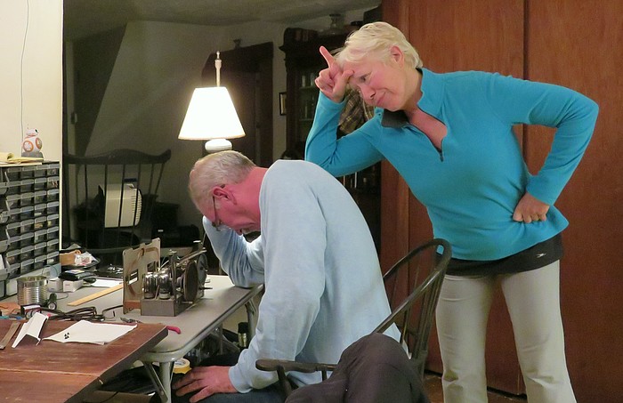
I "shared the experience" with Andrea, thinking I would
impress her with my handiwork. The same thing happened last
year with the Westinghouse "Refrigerator Radio." I
couldn't turn around and look at her. If I found out she was
making that "loser" gesture at me I'd be humidified. |
|
|
|
|
|
LOOO-ZERRR! |
DOH! If I don't get this
set to work, all that sanding and
painting of the case was for nothing. There are seven coils
in this radio. What if one burned open? The IF cans were
checked before I started, but the oscillator coil is giving
strange results, as well as the 14C7 RF amplifier tube.
Pins 3 and 4 should read about 50K ohms each, but read wide
open.
I now have a bit of anxiety. What if I never get it to work? |
|
|
|
|
|
|
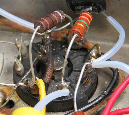
| This 10KΩ resistor is testing INFINITE
ohms. It is between pins 2 and 3 of the 14C7 vacuum tube. I
never gave a thought to it. It appears to be perfectly fine. Almost everything in the radio
was replaced, but I didn't even glance at this. |
|
|
| The 10K resistor was
replaced. The radio was turned on and emitted a loud
buzzing. NOW what?? On a hunch, I unplugged the LED light shining on the
radio and... |
|
|
|
|
|
|
IT WORKS!!! |
|
The buzzing was caused by the LED light bulb in
the work light! |
|
|
|
| |
|
|
| |