Modern Radio Laboratories
® /Alfred P. Morgan Mash-up
|
|
Making the coils.
Determining which wires go to which pins. |
|
|
|
Elmer Osterhoudt and Alfred P. Morgan both give
instructions on how to wind the coils and both are hard to
comprehend. Morgan advises to just buy the coils, but
gives instructions on how to wind a coil on a Bakelite coil form.
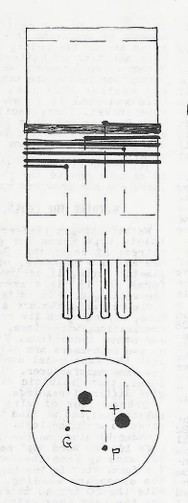
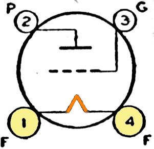
Elmer wants you to follow the diagram on the left, drawn in his
typical style with no perspective. Are you going to buy blank coil forms and wire, and try to
wind a coil based on this perplexing drawing? Better just buy the coils already made from MRL. This lousy drawing
is good marketing.
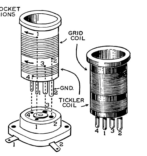
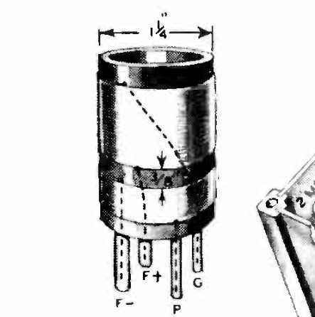
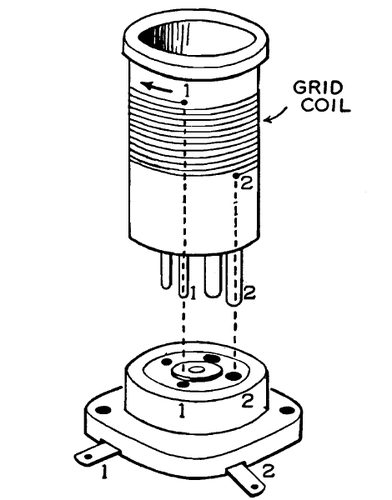
The superior drawing in Morgan's book is still
confusing. Above, on the far right, pins 1 and 2 on the coil are closest to
you, and pins 2 and 3 are the fat pins. Once you see
that one fat pin is in the rear, the drawing becomes clearer.
|
| |
|
|
|
| |
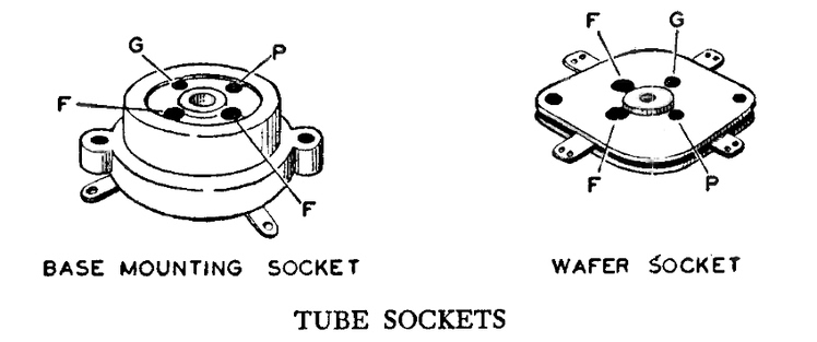
The
circle in Elmer's drawing is the socket. If you mentally tilt
the circle and compare it with the Morgan socket, "P" is pin 1.
Elmer used the designations for Grid,
Plate, Positive Filament (+) and Negative Filament (-).
The reasoning behind this is shown further down this
page. |
|
|
|
NOTE: The larger of the two coils is referred to as the Grid or
Secondary coil |
|
|
|
|
|
|
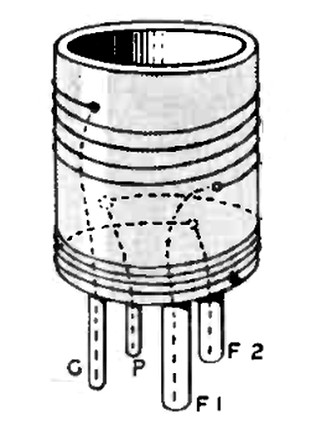
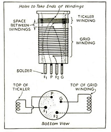
These drawings, from two
articles in Radio Builders Manual
published in 1934, show the same pin connections as in
Morgan's drawing. (Ignore the letters and follow the coil connections to
the pins.) Note that the coils are rotated a quarter turn when compared
with the Morgan drawing.
Once again we
see pins labeled for a filament, F- and F+, or
F1 and F2. Why? After 100 years these
designations, which were once common knowledge
to a radio fan, have me flummoxed and
bewildered. |
|
|
|
| |
|
|
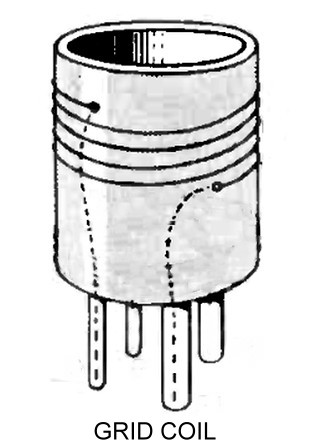
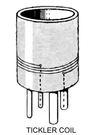
| This is so confusing to me
that I edited the drawing. Each coil is
connected to a fat pin and a thin pin and both
are wound in the same direction. It doesn't
matter which direction as long as they are both
the same. The tickler can be on the top or the
bottom. You can't just pick any pins you want, or
you may end up with a coil that doesn't work. |
|
|
| |
|
|
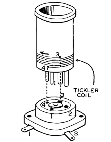
| The Morgan coil
drawing simplified. |
|
| |
|
|
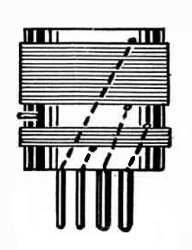
| From "The Radio
Amateurs Handbook" 1929. |
|
| |
To complete the confusion, the numbers on a four
pin socket don't match up with the numbers in
Morgan's drawings. If I had never seen a real coil, I'm not sure I could
make one based on these drawings.
This explains the guys who say, "I built one of these when I was 10
years old. I've spent my career in electronics thanks to Alfred P.
Morgan." These kids were winding radio coils from
incomprehensible instructions. It is no wonder they were successful
in life. (Actually, one guy who built the Morgan set told me he
became a Geologist, so the "career in electronics" theory is not
rock solid. Get it? "rock" solid. Never mind.) |
The coils are "standard" in the pin configuration. (The only reason
I state this is that Morgan said to buy the coils, and if there
wasn't some standard at the time, the radio wouldn't work.) A 1935
Bud Radio Products catalog states that their coils can be
used in any circuit specifying a four prong coil, so this
configuration dates back at least to 1935, and Elmer Osterhoudt had
been making them since 1932.
|
|
|
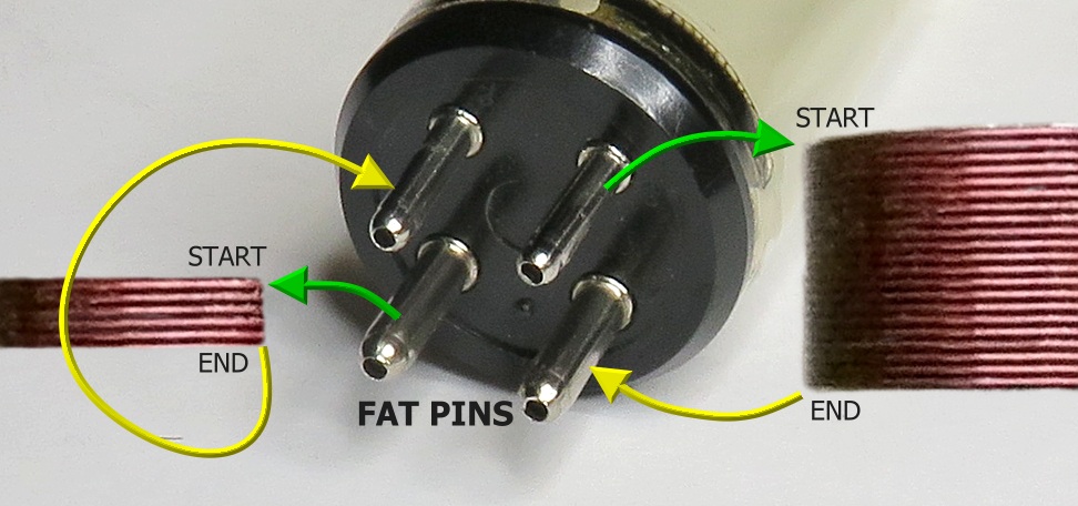
There are two
fat pins and two thin pins. Logically, you'd think that the big
coil would connect to the fat pins and the small coil would connect
to the thin pins, but that's not the standard. Each coil is
connected to a fat pin and a thin pin.
So why is that? A four pin vacuum tube has the filament on the fat
pins. If a coil was wound across the fat pins and you
accidentally plugged it into a tube socket, it would heat up
while putting a dead short across the source of the filament
voltage. There would be a contest inside the radio to see
which would turn into a puff of smoke first; the
transformer, the coil, or the wires going to the tube
socket. |
|
|
|
|
|
|
|
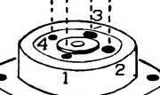
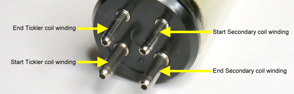
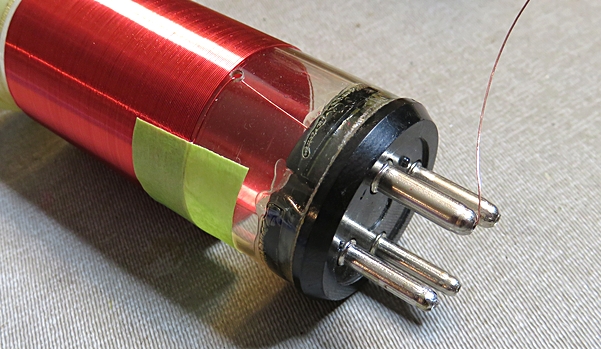
| The pin connections of the two
coils (compare to the drawings). Wind
both coils in the same direction. For example, if you wind the
secondary coil down from the top, starting on pin 1 and ending on pin
2, then also wind the
tickler down from the top, starting on pin 3 and end on pin 4. Both
coils must be wound in the same
direction or the radio won't oscillate. Leave 1/8" between the two windings. |
|
|
|
|
|
|
Here's another way to visualize it. |
|
|
|
|
This diagram from the March 1935 issue of Popular Science,
page 59, shows the pin labels.
Ironically, the article states there is
no standard that determines which pin connects to which coil. |
|
|
|
Another Mystery Solved
Why are the pins designated with letters?
|
|
|
|
|
|
|
|
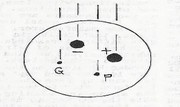
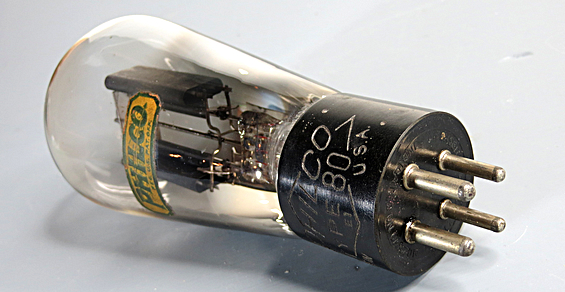
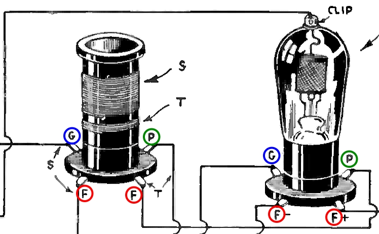
The logic behind the pin designations on a coil is that the coil used a
tube socket. When you look at a
schematic or pictorial of an old radio, the designations on
the coil don't seem to make much sense unless
you see the coil together with a vacuum tube, as
shown above. The coil socket has the same
labels.
NOTE:
P and F+ connect to the smaller "Tickler" coil. G and F- connect to the main tuning coil, or "Secondary." |
|
|
|
|
|
|
|
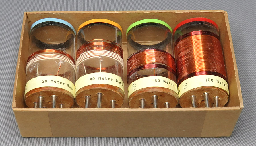
A set of MRL coils.
|
Elmer put the tickler winding on the top, Alfred Morgan put his on the bottom. It
doesn't really matter as long as you wind the tickler and secondary coils
in the same direction.
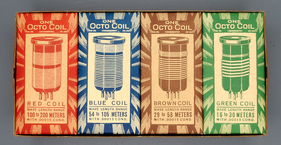
Notice that the MRL coils are color coded.
The only evidence I can find that there was an industry standard for
the colors is that OCTO and a company named Edwin I. Guthman & Co.
both used the same colors, red, blue, brown, and green. Bud
"Lo-Coil" shortwave coils are similar to the OCTO coils in
constructions and wavelength covered, but their coil forms are red,
green, brown and black. |
|
|
|
|
|
|
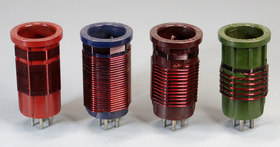
"OCTO" brand four pin coils. Red, blue, brown and green.
The red coil might tune similarly to the
red MRL coil, but the other colors don't match. The tickler
winding are on top, like the MRL coils.
|
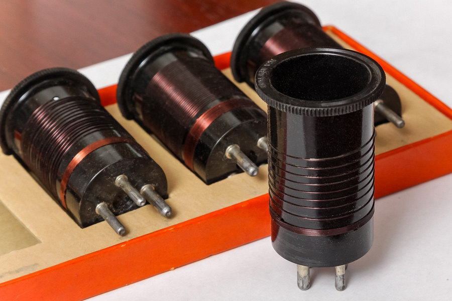
Since Octo Coils had been around since about
1927, we can consider them to have a "standard" pinout, even if
it's a defacto one. MRL coils pins agree with the Octo Coils.
The side of the box states that this set costs $5. If they
were made in 1930, that's the equivalent of $97 in 2025. MRL coils
were $1.50 for a set of four, or $29 today. They aren't the same
quality, but work better due to the celluloid coil form. |
|
|
This set of Bakelite coils made by Insuline Corporation Of
America don't use any color code at all. |
|
|
|
|
Here is
MRL / Morgan comparison data for the AM Broadcast Band coils. Two coils are needed to cover
the band. |
| |
|
| |
Variable
Cap |
Secondary
Coil turns |
Wire
Gauge |
Tickler
Coil turns |
Wire
Gauge |
| COIL 1 |
|
|
|
|
|
| MRL |
10 -
140 |
84 |
28 |
14 |
28 |
| Morgan |
10 -
365 |
70 |
30 |
20 |
30 |
| |
|
|
|
|
|
| COIL 2 |
|
|
|
|
|
| MRL |
10 -
140 |
170 |
34 |
25 |
34 |
| Morgan |
10 -
365 |
150 |
34 |
45 |
34 |
|
Notice Morgan uses less turns on the secondary and
more on the secondary, but he used a variable capacitor that is
double the value Osterhoudt used. Osterhoudt tells us the first MRL
coil will tune from 950 kHz to 2100 kHz and the second coil tunes
from 436 kHz to 1000 kHz. The forms are 1 3/8" in diameter.
|
|
|
|
|
|
|
|
|
|
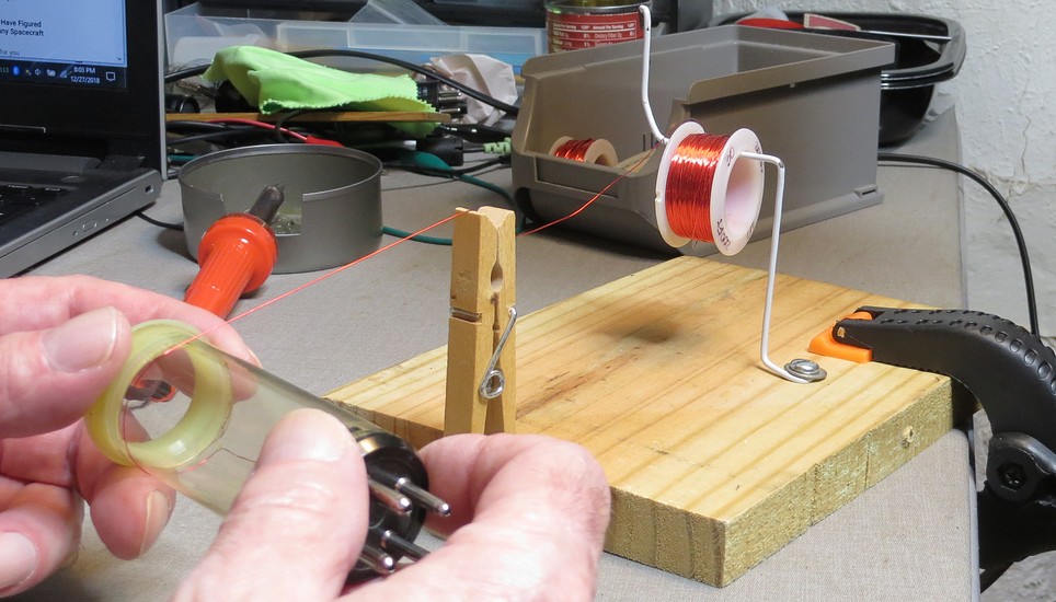
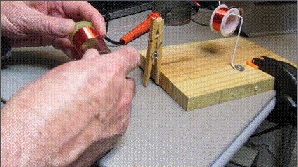
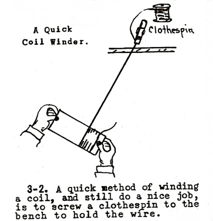
To wind the coil you need tension on
the wire. This can be done by passing the wire through a hole in a
clothespin (an idea from one of Elmer's handbooks).
Scrape the insulation from the end of the wire. Drill or melt (with
a hot pin) a hole
in the top of the coil form, pass the wire through the clothespin,
into the hole, and into pin 1.
Heat the pin with a soldering iron. Solder will wick into the
hole, soldering the wire to the pin.
When the coil is wound, hold it in place with a piece of tape. Drill
or melt a hole in the form, scrape the insulation from the end of the wire, and pass the
wire through the hole and into pin 2. |
|
|
|
|
- Click on image -
MRL coil winder from HB-6 "How To Make Coils."
|
|
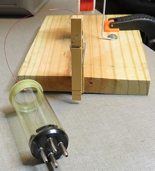
After you wind the main coil, wind the tickler coil
in the same manner. I found that trying to get the bottom tickler
winding wire into pin 4 was almost impossible due to how close the
hole in the bottom of the coil form was to the pin. The fix for this
is to hold the winding in place with a piece of tape and leave about
a foot of wire on the end. Scrape off the insulation at the
appropriate place. Push the wire through the hole in the form, bring
it out the top, then loop it around and insert it into the pin. Pull
it tight and solder. |
|
|
|
|
|
|
The completed coil. It tunes from below the broadcast band up to about 1100 kHz.
Two coils are needed to cover the entire band. |
|
|
|
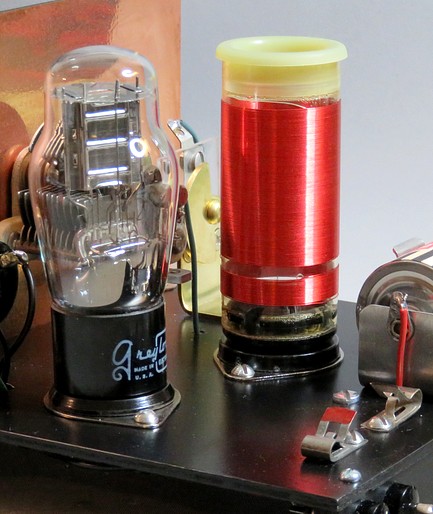
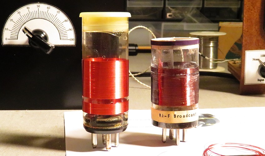
| The second coil, on the left. It tunes from
around 900 kHz to 1750 kHz. Next to it is an MRL coil that covers
about the same range. I try not to handle the Elmer Osterhoudt MRL coils too much.
The coil on the left is wound on an MRL form made by Paul Nelson in
2015. |
|
|
|
|