Modern Radio Laboratories
® /Alfred P. Morgan Mash-up
|
|
|
|
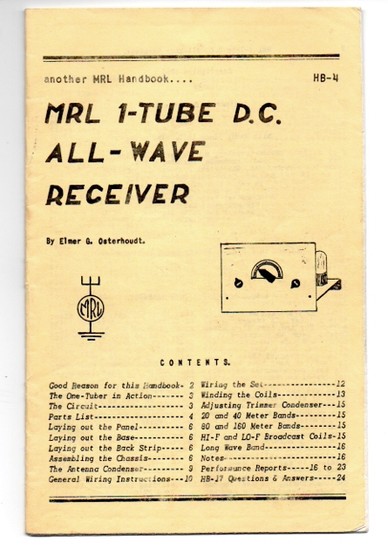
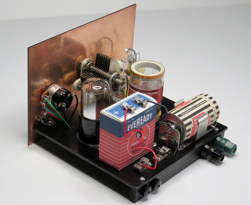
A Modern Radio Laboratories® 1 tube regen radio, designed in 1940 by Elmer
Osterhoudt.
This one was built in December of 2018. Though the front is a duplicate
of the MRL radio, the circuit has been slightly altered. |
|
|
|
|
|
The radio was built according to instructions in Handbook 4,
published by MRL® in 1953. |
|
The Handbook can be found
here. |
|
|
|
|
|
|
---
Click on the page for a larger version you can read. --- |
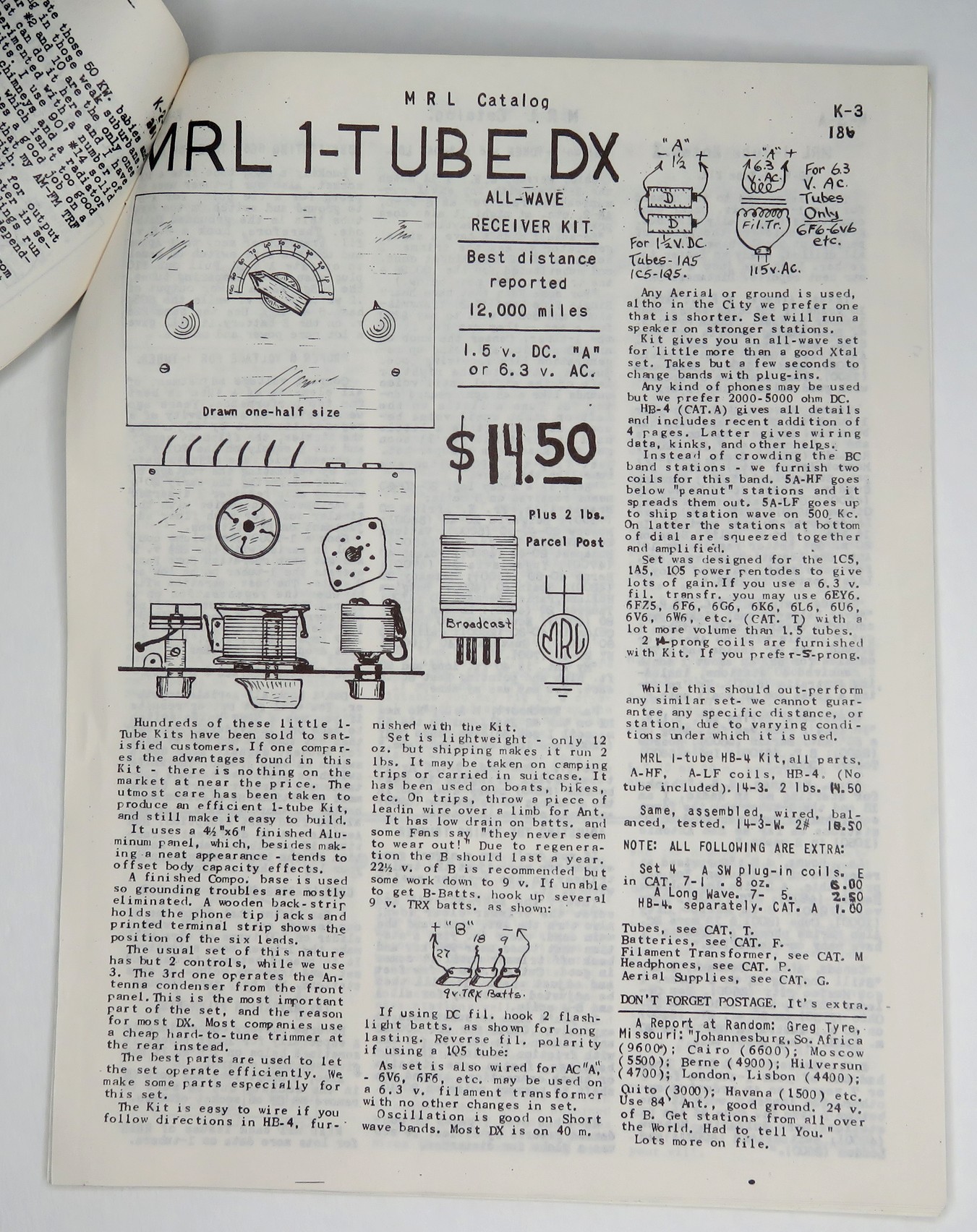
In the 1953 handbook, Elmer states that many
hundreds of kits had been sold. It had only been 13 years since he
published the plans. How many more were sold in the next 33 years?
How much did a kit cost in 1953?
In the 1979 catalog the kit was $9.50. In 1986 it was $14.50. If you
adjust both of these prices for inflation (2018) the result is
approx. $32.70. $32.70 is equal to $3.55 in 1953.
Elmer had a knack for calculating inflation, but we won't know for
sure till a MRL catalog from the 1950's can be found.
The average annual income in 1953 was
$4,200.00, or about $80.70 a week before taxes. It probably wasn't a
big expense to spend $3.55 out of your $80.70, which was Elmer's
goal. Of course, if you were 12 years old it may have taken
months to acquire the $3.55.
Government figures found here. |
|
|
|
|
|
The front panel is a 4.5" x 6.125"
double sided printed circuit board. The manual says to use a 4.5" x
6" painted aluminum panel. The fact that the measurement is off by
1/4" is of no concern.
Elmer Osterhoudt used whatever he
could find that would keep the costs down for his customers. I have
not seen two of these MRL made kits that are alike.
One would think that if a part of your business was a one tube radio
kit, you would obtain 1000 front panels, 1000 variable capacitors,
1000 tube sockets, 1000 coil sockets, 1000 vacuum tubes, 1000
resistors, 1000 capacitors, etc. so you could whip up 1000 radio
kits, but apparently Elmer didn't operate that way.
So basically, it doesn't matter what parts are
used because there was no "standard" set of parts. |
|
|
|
|
|
|
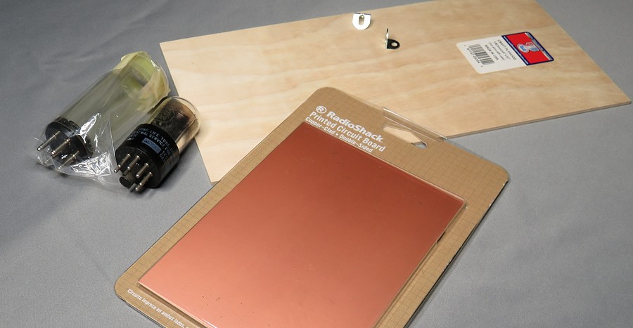
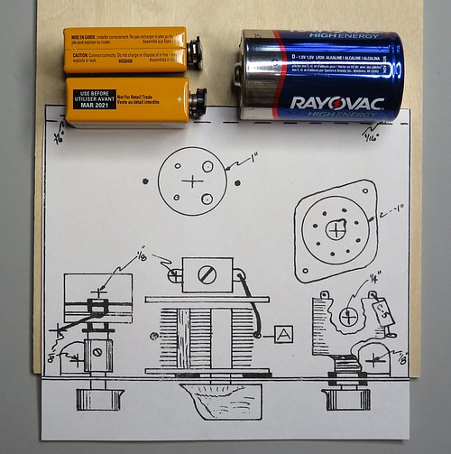
Collecting parts for the radio. The front panel,
base, 1C5 vacuum tube and a coil form.
If you need to cut the printed circuit board, see
this. |
|
|
|
|
|
|
|
|
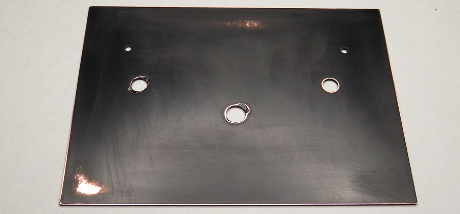
The front panel after painting and sanding. Why
was it painted and then sanded? A mote of dust started a chain
reaction.
The paint job was beautiful, but while the panel was drying a speck
of dust landed on it. I noticed it a few hours later and thought I
would just pick it off with my thumbnail. My thumbnail made a small
gray spot where the speck had been. No problem, I'll give it another
coat of paint.
The instructions on the paint can say to wait 24 hours before
recoating. Why? It gave no reason. 12 hours had passed, that was
long enough, so I gave the panel another coat and watched as the
paint crinkled up. I suddenly understood the instructions.
I waited an hour for the top coat to dry and began sanding it off
with 1000 grit wet sandpaper. Since I'm such a clever guy, when I
got down to the base coat I thought it would be a good idea to heat
the panel up under a light bulb and speed up the curing process.
After an hour it was ready! The heat had surely knocked 12
hours off the 24 hour waiting period.
I gave the panel another coat of paint while reflecting on how
clever I was, then saw the new paint crinkle up again in several
different places. DOH! More sanding followed.
I reluctantly waited the required 24 hours. It's December, 2018. To spray paint
this I need to take it outside, paint it, then bring it inside. It
is cold and breezy and stuff is blowing around out there. Another
coat of paint and I quickly brought it inside. I didn't go near it
for two hours. All I needed was for an eyelash or something to land
on it.
After two hours I picked it up and there was a SCRATCH on it! I must
have bumped it against something in my haste to get it indoors. More
sanding.
To make matters worse, I had painted the
front of the PCB while it was lying on a piece of cardboard. The back had
to remain exposed copper. While bringing into the house, the
PCB moved when I bumped it, and the copper back picked up black overspray from the cardboard.
More sanding. |
|
|
|
|
|
|
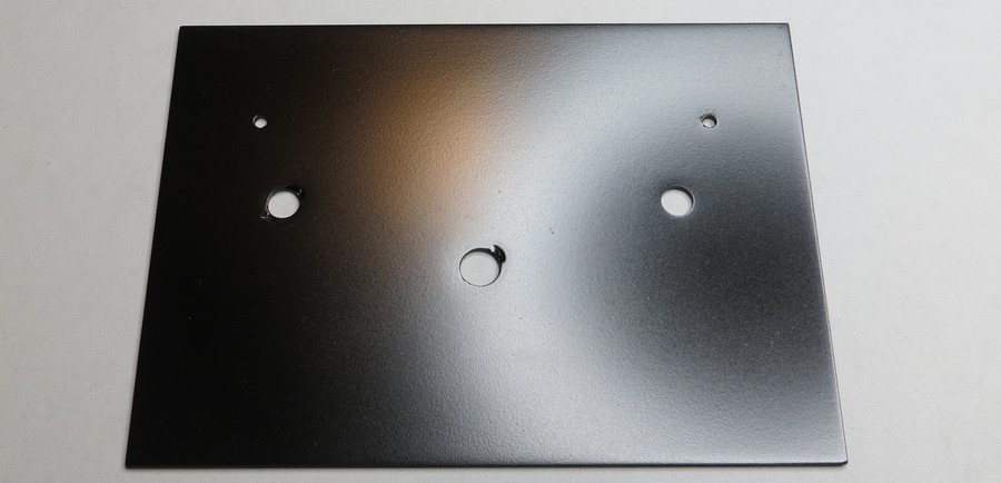
Finally got a nice paint job on the 5th try. Any specks on
it are going to STAY on it! |
|
|
|
|
|
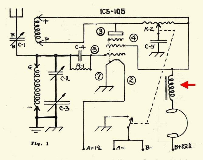
The schematic. An RF choke will be added before the headphones
to keep the radio frequency energy out of the headset cord. Without
this choke, there are problems when you move the cord.
Elmer used a choke in a similar circuit in Detail Print 29. (Here)
Capacitor C-2 isn't
needed because the correct value of C-3 will be used (see Page 4 of
HB-4 for the reasoning behind C-2).
|
PARTS LIST
C1 = Two plate variable capacitor
C2 = 25 - 280 mmfd variable mica trimmer
(not needed if C3 is 140 mmfd)
C3 = 140 mmfd or 365 mmfd variable capacitor
If C3 is 356 mmfd, C2 and C3
are set so the total capacitance is 140 mmfd.
C4 = .0001 mfd mica capacitor (100 picofarad)
C5 = .00048 mfd mica capacitor (480 picofarad)
R1 = 2.2 megohms
resistor
R2 = 0 to 10K - 50K (linear taper)
|
|
|
|
|
|
|
The handbook doesn't say a lot about the
batteries. Elmer states two or three nine volt batteries can be
connected in series for the B+. He also says that two dry cells in
parallel provide the filament voltage. A single modern alkaline
produces more output current than two 1950s dry cells, so only one
is needed.
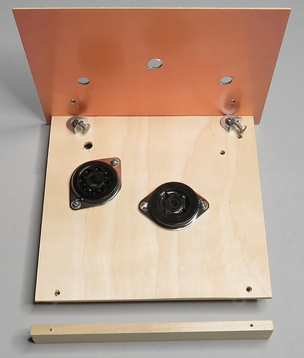
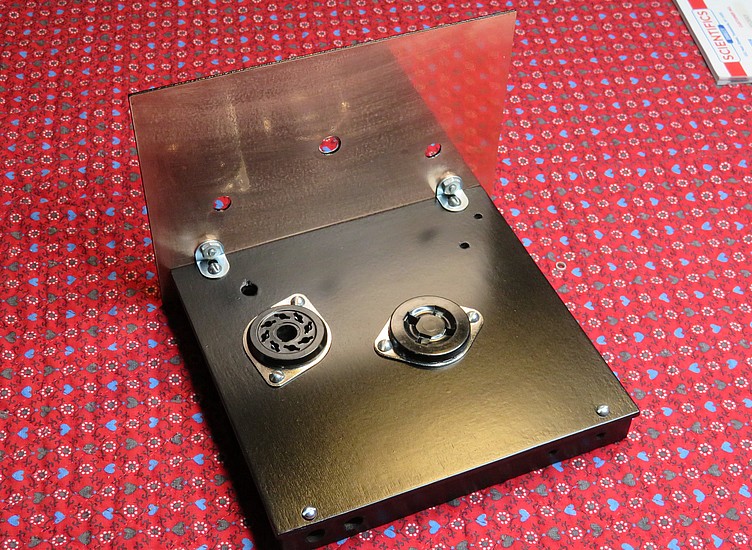
The radio was originally designed so the batteries sit somewhere behind
it on the table. How far away are the batteries? Doesn't that affect
the circuit in some way? By lengthening the base 1.5 inches, the batteries can be
placed on the base.
At the bottom of the right-hand photo is the back strip. On Page 6
Elmer says to make it 3/4" high. On Page 12-B he says he finds
11/16" to be better. This one has been painstakingly cut
by hand to 11/16".
Why is 11/16" better than 3/4"? I think it gives some insight into
Elmer Osterhoudt's methods. I'd bet he made 1.5" wide strips of
plywood, then cut them down the middle. Due to the thickness of the
saw blade you get two 11/16" strips, not two 3/4" strips.
Another question: why are the page numbers in consecutive order till you get to
Page 12, and then there are pages 12-A to 12-D?
It's because he
printed all his handbooks with a lithograph machine and once the
lithograph plates were made, they couldn't be easily edited. So he added to
them, starting on Page 12. |
|
|
|
|
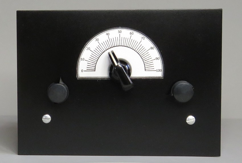
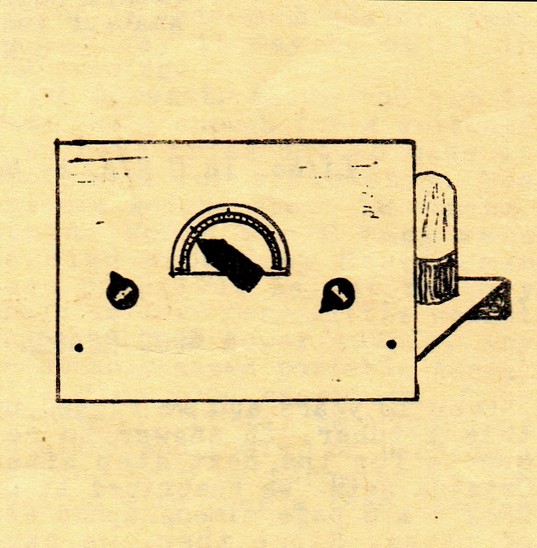
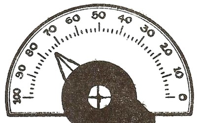
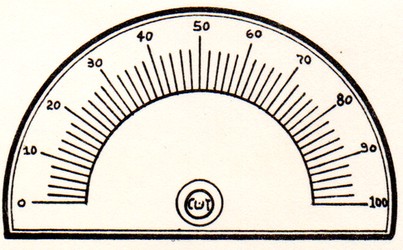
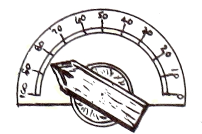
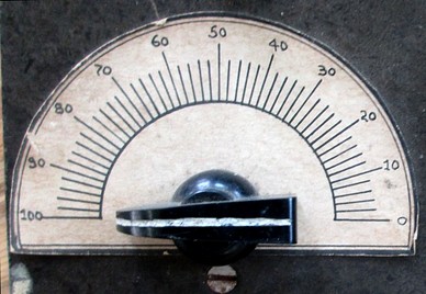
| On the left is the dial scale shown in the
handbook, from 1953. On the right is the dial scale from a kit sold
in the late 1970s. Notice the scale from 0 to 100 is inverted in the
earlier drawing. What is the reason for this? Elmer must have had
variable capacitors with a counter-clockwise action in 1953. |
|
|
|
|
|
The dial from the picture in the MRL catalog also has a
reverse scale, as does one from a 1971 MRL No. 10 crystal set.
In all four pictures, "50" is in the same spot. What are the odds? |
|
|
|
|
|
Of course, the paint job on the base came out OK
- because I
didn't give a crap about it. It's painted with Krylon black satin paint, the same
paint as the front panel. I entertained the idea of making this look
as smooth as Bakelite, but it was holding up the assembly of the
set.
After an email discussion I had with a guy named Sloane Freeman, I
had some concern about the lampblack in the paint pigment. (Sloane
was on good terms with both Elmer Osterhoudt and Paul Nelson of MRL.)
Lampblack is conductive. The first thing the signal from
the antenna will encounter is the base, via the antenna connector
which will be screwed into it. (The alleged conductivity of the
paint can't be measured with an ohm meter, but things work
differently at radio frequencies.)
Now I'm all paranoid and what not. I'll get the radio to work, kine
hora, by changing the antenna connector. (That's how Sloan would say
it, always including "kine hora" to ward off the Evil Eye.)
If you look at Elmer's "Compo" bases
and panels they are coated with a black paint. Elmer wouldn't have painted
the panels of his crystal sets or other kits with a conductive paint,
so what was the pigment he used? It's a mystery; even Sloane doesn't
know what it was. |
|
|
|
|
|
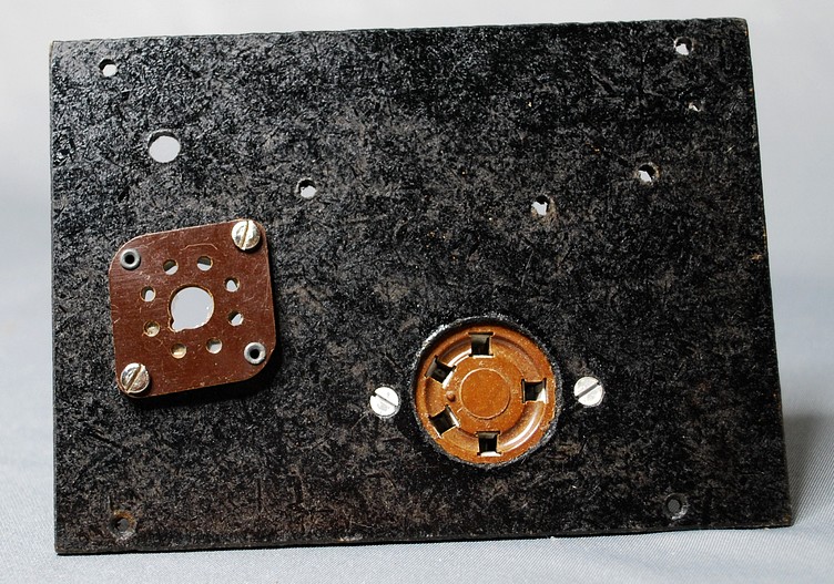
Base for MRL One Tube Radio made by Elmer Osterhoudt in the
1970s
|
| NOTE: Later reading of MRL literature showed that
concern about the black paint being conductive was completely
unfounded. Elmer himself switched to black spray paint from a can
after testing it. |
|
|
|
|
|
|
|