The Experimental Radio Project
|
|
|
|
|
Andrea |
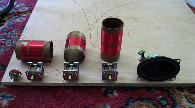
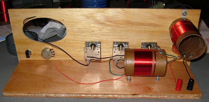
My girlfriend Andrea bought me a nice piece of plywood at
Home Depot to use as a base.
The
components
were placed on the
plywood to get a sense of the size, then she cut it to size. |
|
|
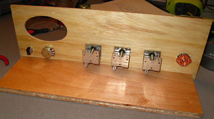
A front panel was made using a 1/8" thick piece of Luan floor
underlayment. This proved to be very difficult to
drill into without
splitting the wood.
Making the front panel and mounting the parts took a whole
afternoon. |
|
|
|
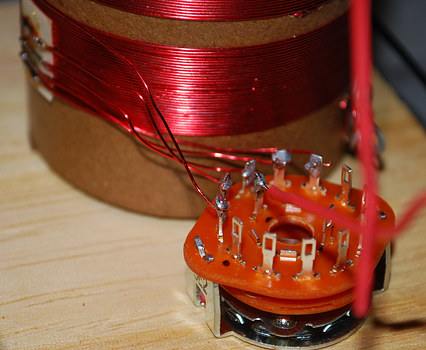
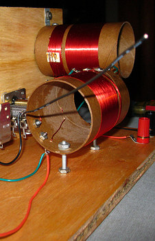
To wire the coil switch the front had to come off. |
The coil switch. |
|
|
|
|
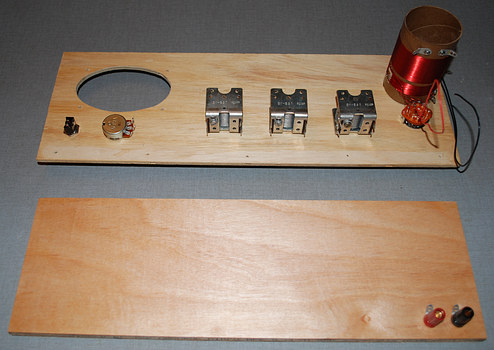
The TANDEM TUNER was built next, along with connections for
antenna and ground. |
|
|
|
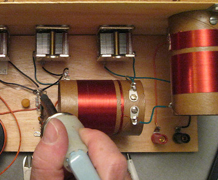
Now it was time to see how well the TANDEM TUNER worked. I had never
seen this circuit before and I was sure I had "rediscovered" some
long lost
circuit that would be interesting to crystal set fans
everywhere. I connected an antenna and ground, then put a crystal
diode and high impedance headphones
across the secondary winding of the second coil. I expected to hear
several local radio stations, but instead only a single one could
barely be heard.
I checked all the
connections and tried every combination of controls but the TANDEM
TUNER wasn't working the way I expected it would. |
|
|
|
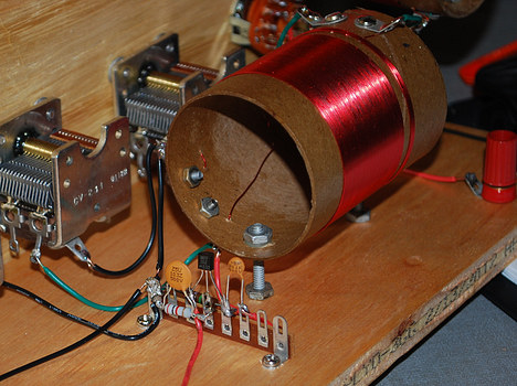
Well if it doesn't work, it must be because it needs an RF
amp.
In this photo one is being assembled. |
The completed RF amp, Version 1.
A Field Effect Transistor (FET) replaces the vacuum tube.
|
|
|
|
|
|
|
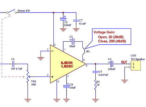
Before any testing was done I built the audio amplifier
using an LM386.
I wouldn't need the headphones for the next test, the rig now had a
speaker.
(or "reproducer" as they called it in 1929)
|
|
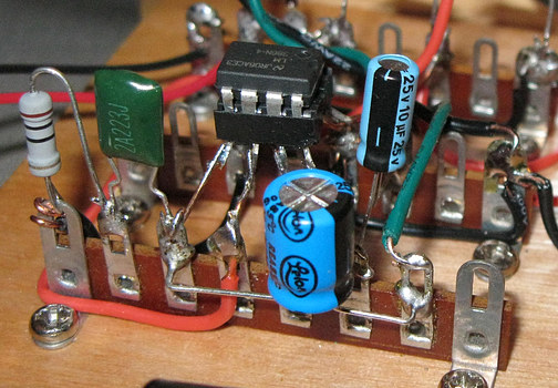
The audio amp, built on two terminal strips. I do NOT
recommend
this method but it gave a certain "look" to the radio.
|
|
|
|
|
|
|
|