|
|
|
|
|
|
|
...the answer was,
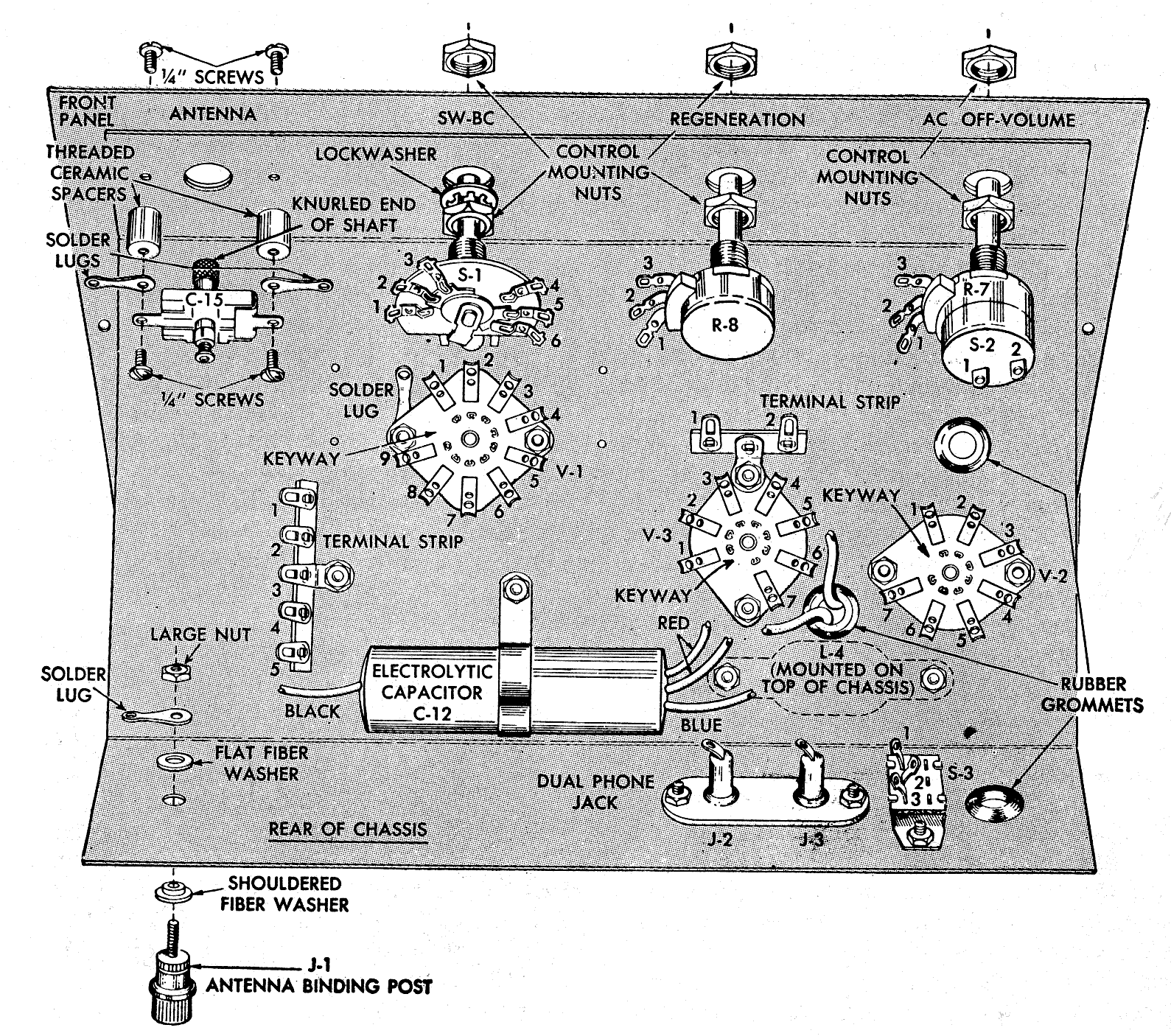
"I have the radio, and the controls aren't mounted like yours. They are mounted with one hex nut behind
the panel so that only a minimum amount of the threaded
bushing extends through the panel. Your suspicions are
correct.
Vince" |
|
|
|
|
|
A few minutes later, Vince
sent this picture. Click on it for full size.
OK, let's think
about this. I wanted to keep the radio original. However, if
James had skipped the steps where he was supposed to mount
the hex nuts, the radio isn't going to look right. He used
the lock washer behind the bandswitch control, but didn't
bother with the hex nut. We'll never know why. Perhaps the
neighborhood bully shook him down for hex nuts.
At any rate, the controls were going to get the hex nuts so
the radio looks right. |
|
|
|
PROBLEM! |
|
|
|
|
|
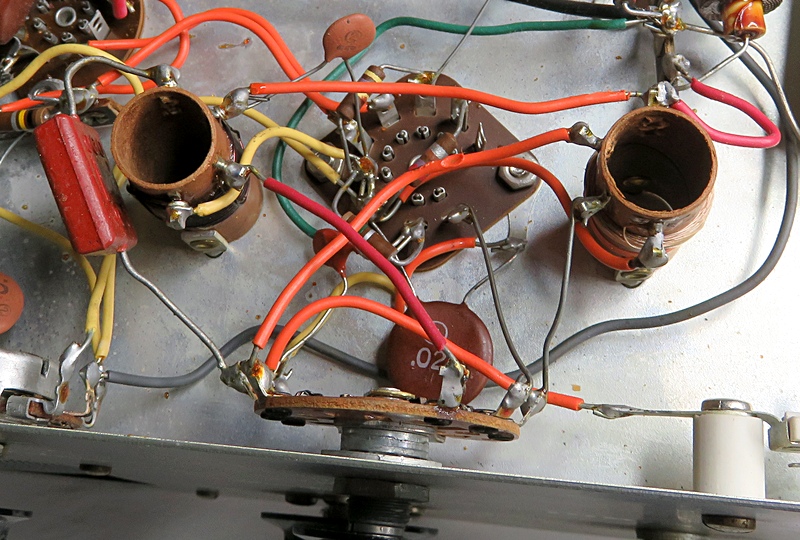
Now there is a
problem. How can you back the bandswitch out with everything
connected to it? You can't, mostly because of the heavy
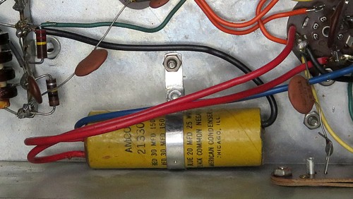
leads on the big brown capacitor on the left. It goes from
the switch to the coil and the leads might as well be pieces
of coat hanger, they're so stiff. Should I start unsoldering everything? What
if something gets damaged?
Just then, this came in from the radio forum: "Did you
try unbolting the coil to see if you could move it and the
switch enough to put on the nut and washer? You might also
have to unbolt the 12AT7 socket. Be very careful with the
connections on the coils. They were really only intended for
one soldering operation.
Jay" |
|
|
|
|
|
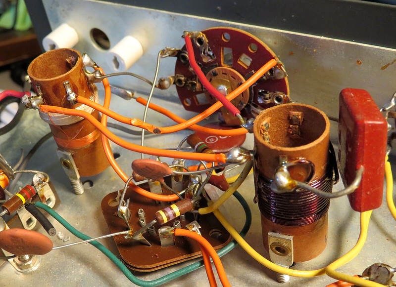
That was the answer! In this photo both coils and the
tube socket have been detached and everything is slowly being backed
out.
|
|
|
|
|
|
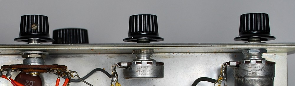
Success! |
|
|
|
|
|
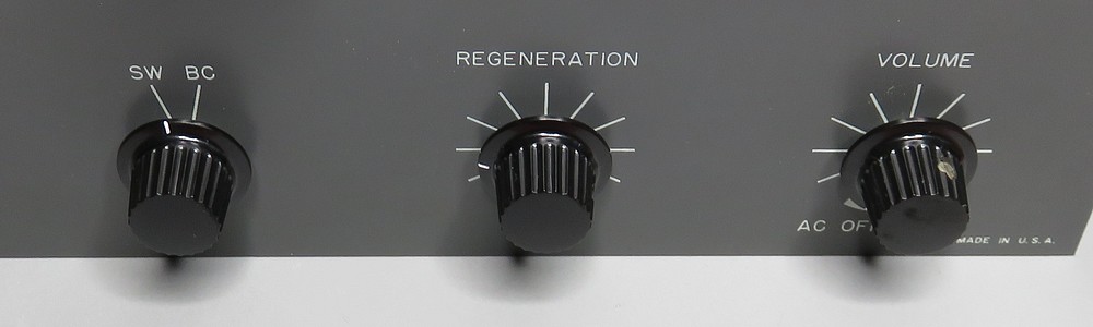
The knobs are now in their
proper positions in relation to the front panel. |
|
|
|
|
|
|
RE-STUFFING CAPACITORS |
|
|
|
|
|
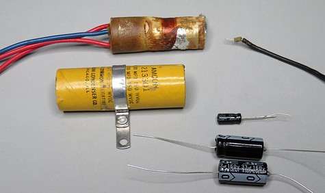
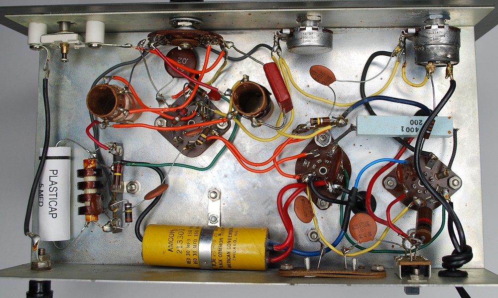
For some reason, James
installed the filter capacitor facing backwards. This means we can
reuse the wire! |
|
|
|
|
|
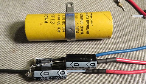
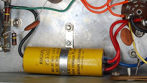
The new capacitors are rated at 160 volts, 10 volts
higher than the old ones. |
|
|
|
|
|
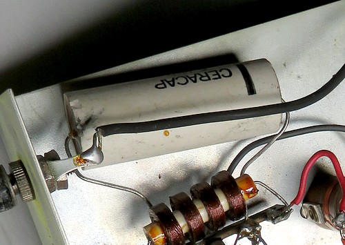
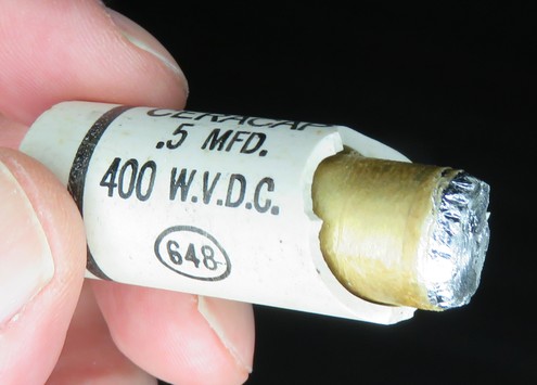
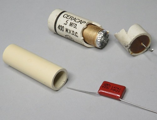
There is a big ceramic covered
capacitor labeled "CERACAP" which I broke while
trying to melt the plastic out of the ends. The wax
inside boiled and the pressure burst the ceramic
apart. Next time, I'll drill a hole in the end
first. Ironically, there was probably nothing wrong
with it.
Interesting that inside is a lit cigar butt. No
wonder these radios smoke. |
|
|
|
|
|
|
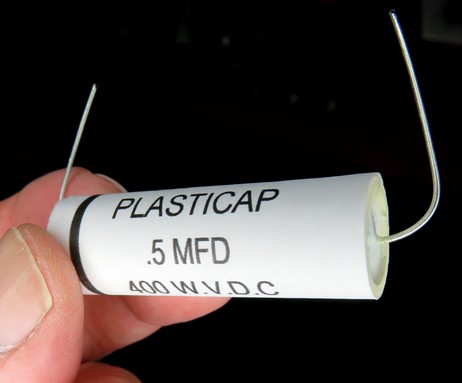
The ceramic was replaced with PVC. It's now
called a "PLASTICAP." |
|
|
|
|
|
| |
|
|
All done.
That was fairly easy. A voltage check showed all the voltages to be
higher than predicted in the manual.
That's because the radio is expecting to see 110 volts AC, but our
outlets are testing at 121 volts AC. |
|
| |
|
|
| Apparently,
this joint had been making a good connection! |
|
| |
| |
|
|
| My only regret. The re-stuffed filter
capacitor had been sitting on the kitchen table for a few
days. I absent mindedly picked it up one night and cut all
the leads to the same length so it would look nice. When I
went to install it, the blue wire was too
short so I had to add a piece of wire. DOH!! |
|
|
| |
|
|
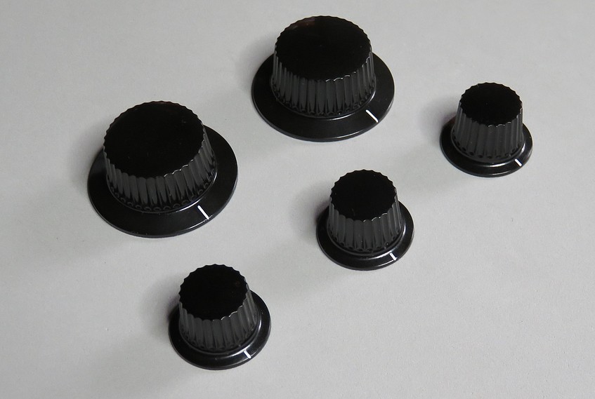
The knobs were soaked overnight in soapy
water and then polished. Thankfully, nobody called me on the
phone during the polishing operation and asked what I was
doing. (Nudge nudge, wink wink.)
The white pointers are craft paint. Very easy to use, you
carefully fill the indentation, let it dry, and then scrape
the excess off with a thumbnail. The results are excellent.
The knobs are marked "DAKA-WARE CHICAGO" on the back. They
were manufactured by Davies Molding Co. and are made of phenolic plastic |
|
|
| |
|
|
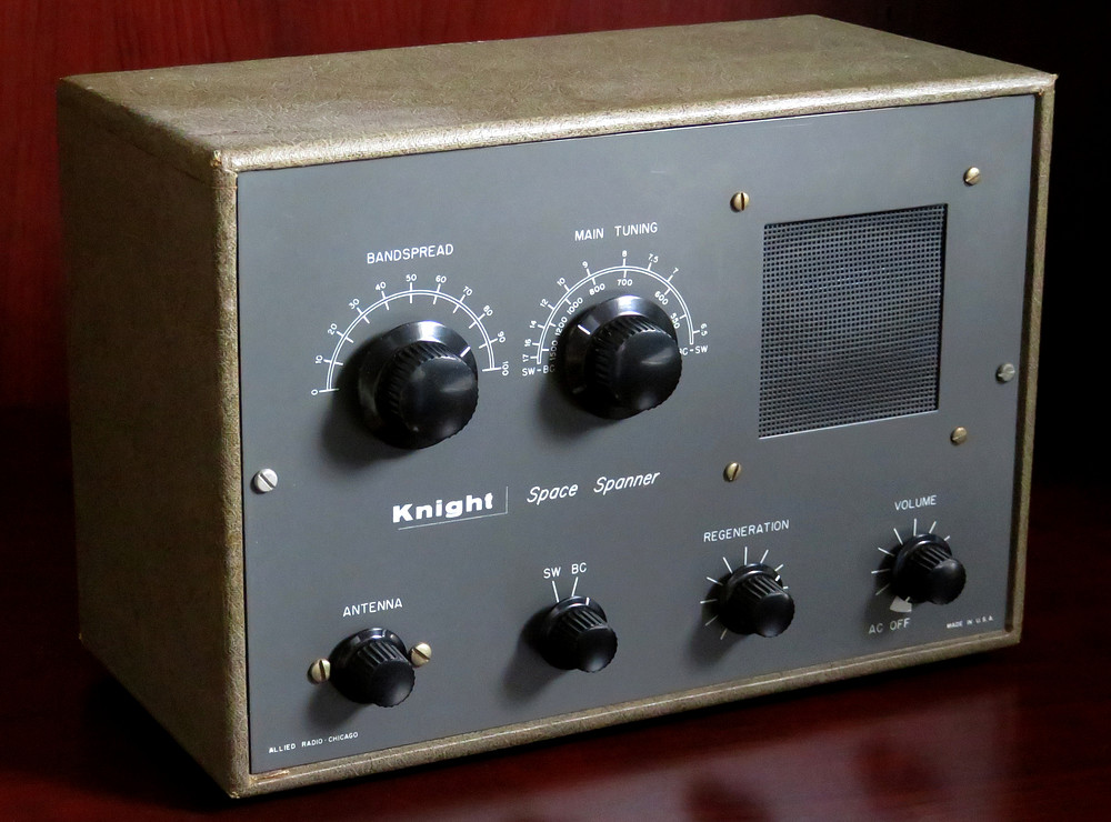
| Refurbished Space Spanner. |
| |
|
|
| Here's a short video showing the
Space Spanner in action. |
| |
| |
|
| |
|
|
| |