 |
1954
Philco clock radio |
|
|
|
|
That was weird. What would cause it to
go dead? Maybe a bad vacuum tube. One by one I swapped all the vacuum
tubes but the set remained silent. Now I couldn't report
back with the AVC voltage, but I had to start
troubleshooting, so I started by checking voltages since
that's what I was going to do anyway. |
|
|
|
|
|
|
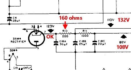
It was
found they were too high coming out of the
rectifier circuit. There were two reasons for this: 1. The
schematic calls for 30, 25 and 20 mfd filter caps and I
replaced them with 33, 33 and 33. This would cause an
increase in voltage. However, the ones I removed were 40, 40
and 40, so I thought it was safe. (I figured the radio
repair guy at Grosse Pointe Radio and
Television knew what he was doing. For all I know he may have
intentionally
sabotaged the set so it would fail later. $$$)
2. The 220 ohm resistor was in reality only 160 ohms.
If the voltages are wrong here, they are wrong all over the
entire radio! |
|
|
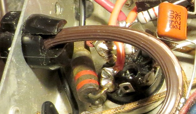
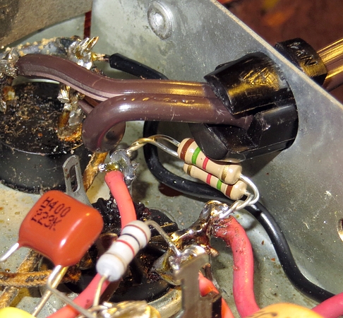
Here's the 220 ohm resistor. I had to
remove the new power cord to get to it.
|
I ordered some 220 ohm resistors and
some capacitors to replenish my parts box. Also ordered some
silver mica caps in case this thing had "Silver Mica
Disease." Because they came from Canada, it took them 17 days
to get here. By the time they arrived I was so busy doing
other things I had almost forgotten about the radio.
Work didn't resume till July 16.
(Ironically, I didn't need any of the parts I ordered!)
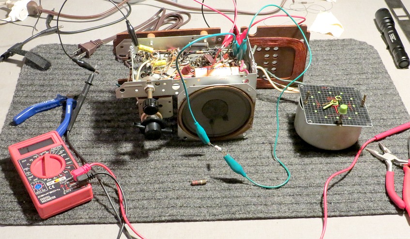
Above, the clock from the bashed radio is being used to
power the chassis while resistors are substituted to bring
down the voltages. |
|
|
|
|
|
|
|
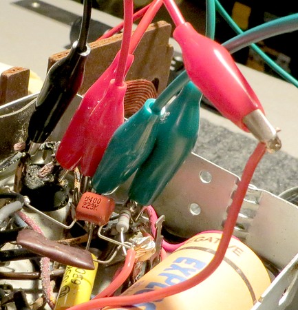
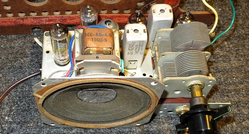
It turned out that 220 ohms
wasn't enough to bring the voltages down. It ended up
with two 1500 ohm 1/2 watt resistors in parallel,
which equaled a 750 ohm 1 watt resistor. The
voltages are within four volts of what they should
be.
I turned the radio on and... nothing. Dead as a door
nail.
It was time to crack open the IF cans and look
inside. Ugh, must be Silver Mica Disease.
|
|
|
|
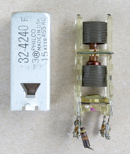
I tried to pop the cover off
one of the cans while it was still attached to
the chassis, but it wouldn't come off. So instead, I
cut one out of the bashed radio to see how it looked
inside.
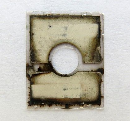
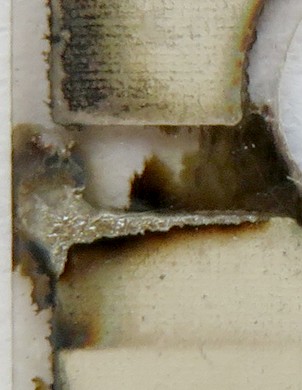
On the right is a close-up of what you can see of
the capacitor. It's a real capacitor made of two
metal plates, not a piece of mica with silver
sprayed onto it.
|
|
|
|
|
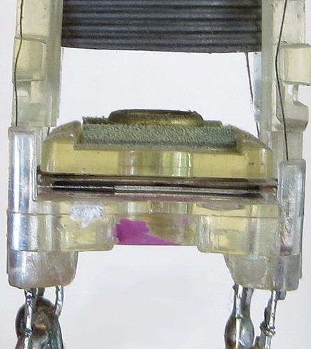
Wait! It's a trick! It's
a deception!! Those aren't metal plates, they're
metal contacts! They touch the silver sprayed onto a
piece of mica. Argh, the silver has migrated.
Why not just make the metal contacts into plates and
put a bare piece of mica between them? I guess it
was easier or cheaper to do it the way it was done.
By the way, the capacitors are 100pf and 80pf,
that's why they are different sizes on the mica.
|
|
|
|
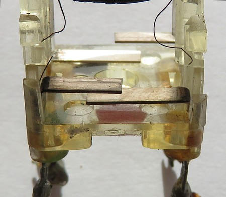
There is the Silver Mica
Disease, on the left. Atoms of silver from one
capacitor are moving towards the other capacitor.
When they meet you get a "pop" in the speaker. As
more and more make the journey the pop turns into a
torrent of static. It doesn't usually cause a
dead radio, but it can happen.
|
|
It seemed I would have to
operate on the IF cans, which I
was dreading. I turned the radio on
and stared at the tube filaments warming up
while I thought about it.
After about 30 seconds it came to life!
Not only was it working, it was working
better than it ever had! Instead of five locals, it
was picking up everything! High power, low power,
local, distant, far away
stations, the entire band was full! Whoo-hoo!! I
must have fixed a bad connection while I was pulling
on the IF can cover. It was fixed!
It did not have Silver Mica Disease after all!!! |
|
|
|
|
|
I told Andrea the radio was working
but it was really bothering me that I didn't know what fixed
it.
I was about to put the chassis back in the cabinet and
turned it on one more time before doing so. It was
DEAD!
AGAIN!
Again?
Yes. AGAIN. DEAD.
Deceased.
It was working a minute ago!!! |
|
|
I wasn't sure what to do at this
point, so I changed tactics. I loudly slammed the silverware
drawer shut. Nothing changed. I spoke to the radio in a
James Cagney voice, then switched to Edward G. Robinson,
see? Still nothing. So I threw my shoes
down the steps after slamming the bedroom door 5 or 6 times.
Out of ideas, I sat down and forlornly started substituting tubes again. When I got to
the 12BA6 the radio came to life! I put the original tube
in, and the set was dead. I replaced it again and the radio
came to life.
I had swapped out the tubes in June and they made no difference.
Why was it working now? I tried it once more. Original tube
- dead radio. Swapped tube - radio comes to life.
Remember, on page one the bashed radio
suddenly came to life and then went dead. I believe both
radios had the same problem with the same tube. Both radios
had their filter caps replaced.
Both sets were operating at higher than normal voltages
and both 12BA6 tubes developed an intermittent problem. In this
case, the 12BA6 had 108 volts on the plate, 48 volts higher
than what it should have been.
Also, the red hot "tube saver" resistor is connected to pin
4, so instead of "saving" the tube, it may actually be
killing it.
So apparently back in June, when I swapped the 12BA6 with
the other, they were
both in their "dead" state.
|
|
|
|
|
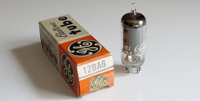
It was off to the garage to find a tube, and I
found this "new old stock" 12BA6 that my buddy Joe Jones gave me years ago. |
|
|
|
|
|
|
The radio now looks and works
like new. I gave it to Andrea since this was all
her fault to begin with. She volunteered to wear the
same gown she had on in the video for this picture. All I can say is that it's a good thing I
wasn't the radio repairman in the video, because the
whole shoot would have been held up for months. |
|
|
| The 12BA6s were retested. One tested
almost new, just as it had in May. I left it in the tube
tester while I went outside and painted the garage window.
When I came back the tube was dead. It was SO dead there was not
the slightest deflection of the meter while pressing the
test button. I tested the other
one just in case there was a problem with the tube tester.
The tube tester was fine. Into the trash can they went. |
|
|
|
|
|
|
| I tried to contact rjd2 to ask
him about the radio in the video but he hasn't answered. The original video is
posted
here. Large .jpg of the
schematic can be seen
here.
Sams Photofact Folder in .PDF can be seen
here.
Riders manual for the radio can be found
here. |
|
|
|
We now return to our regularly scheduled program. |
|
|
|
|