|
"Peebles
Originals" PO-103 Antenna Tuner |
 |
|
|
|
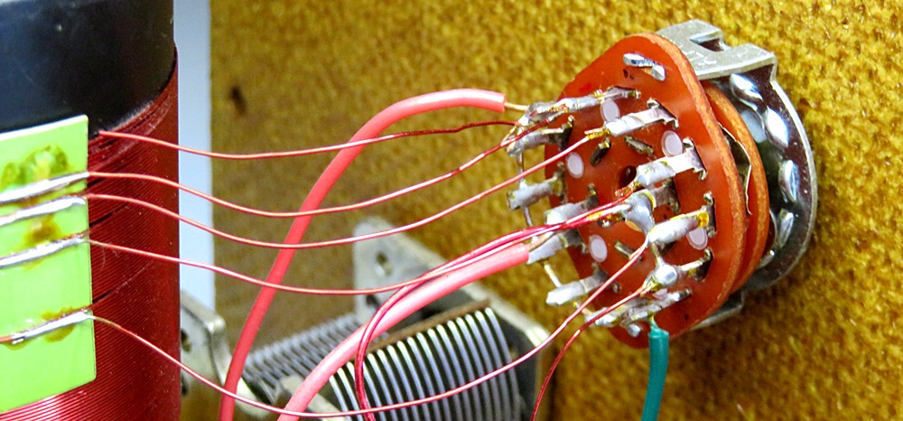
ANTENNA TUNER ROTARY
SWITCH |
|
|
|
|
|
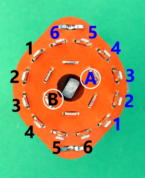
The ingeniously connected rotary switch. |
|
|
|
|
|
|
|
|
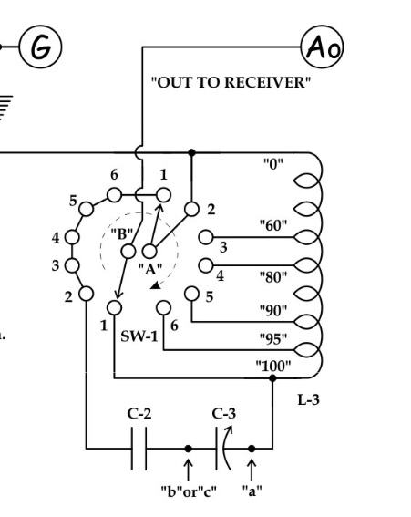
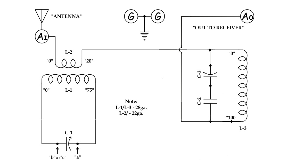
What is going on
with the switch on the antenna tuner? I'm trying to
visualize it mentally, but I'm having trouble. When
the switch is in position 1, terminal 2 of switch A
is connected to terminal 1 of switch A, which is
connected to terminals 2,3,4,5 and 6 of switch B. What does that do?? This is
blowing my mind.
Below are equivalent schematics with the switch in
position 1, 2, 3 and 5 which give a clearer idea of
how it works. |
|
|
|
|
|
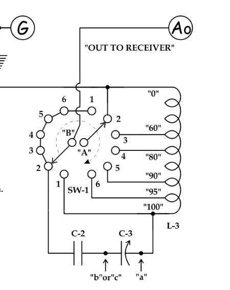
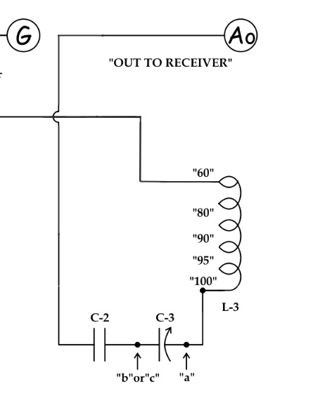
SWITCH IN POSITION 1
|
|
|
|
|
|
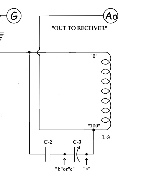
If we remove the switches while they are
in position 1, the circuit looks like this. Much easier to
visualize! |
|
|
|
|
|
|
Moving the capacitors in the
schematic gives a clear picture of them in parallel with the
coil. |
|
|
|
|
|
|
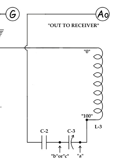
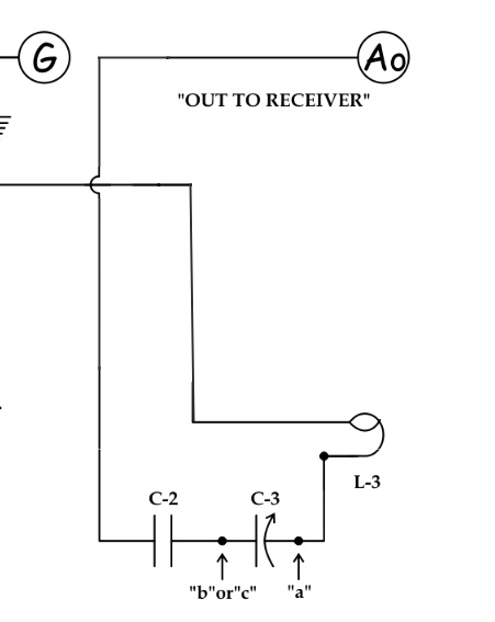
SWITCH IN POSITION 2
|
|
|
|
|
|
Position 2 is selected.
Notice that switch A is now connected to nothing at all. If
we remove the switches, we see that the capacitors are now in series with the coil.
They've gone from being in
parallel to being in series with a single turn of the switch! |
|
|
|
|
|
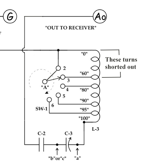
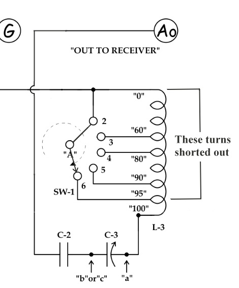
SWITCH IN POSITION 3
|
|
|
|
|
|
Position 3 is selected.
Since all the terminals on switch B are connected together,
we can remove it in the drawing. On the right, we have also
removed switch A so we can see what the circuit looks like.
Switch A has shorted out 60 turns of the coil, making a 40
turn coil. |
|
|
|
|
|
SWITCH IN POSITION 5
|
|
|
|
|
Position 5 is selected. Switch A has
shorted out 90 turns on the coil, making a 10 turn coil. On
the right we see the circuit without the switch.
Positions 5 and 6 are used for shortwave. |
|
|
|
|
|
|
|
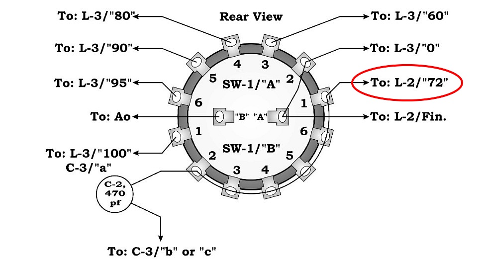
Connecting The Switch
|
|
|
|
|
The switch in the instructions probably won't
match any switch you can buy today. So how do you connect it?
First of all, the connection circled in red (A1) doesn't
exist, so ignore it. It's not on the schematic and L2 doesn't have
72 turns. |
|
|
|
|
|
Obtain a 2 pole 6 position switch. Select which side
will be Switch A and which side will be Switch B. Use an
ohmmeter to find terminal 1 of each side, and mark them.
(Make sure the switch is turned fully counter-clockwise to
position 1).
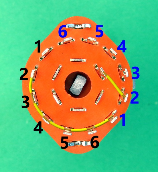
Then just follow the drawings in the instructions. It will
be easier to wire if you make the connections shown on the
right before installing the switch.
Don't forget, you're looking at the back of the switch, so
the numbers will be counter-clockwise. |
|
|
|
|
|
|
| |