|
|
|
|
|
|
|
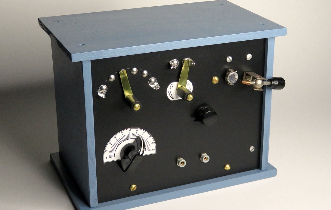
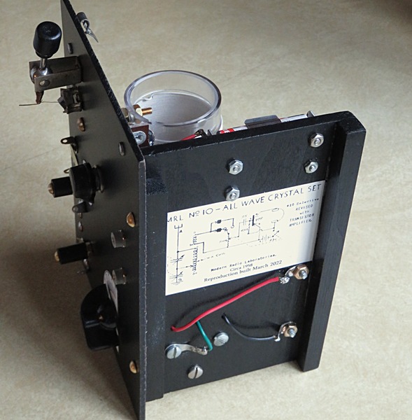
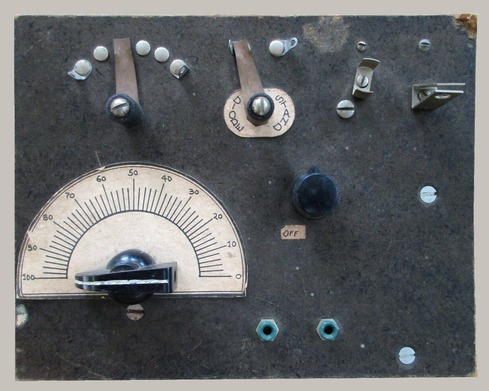
MRL® No. 10 All Wave Amplified
Crystal Set replica. |
|
|
|
|
|
Front View. |
Originally developed
and sold as a kit by Elmer Osterhoudt of Modern Radio Laboratories,
the MRL No. 10 All Wave Amplified
Crystal Set first
became available sometime around 1957. This replica was built in
March of 2022. The price in 1957 isn't
known, but in 1972 the kit sold for $8.50, which is about
$58.00 in 2022. Considering what I spent acquiring parts for
this, the $58.00 price makes me feel a little better. Let's
just say that this little crystal radio cost me about $16.00 in 1972
dollars. |
|
|
|
|
|
|
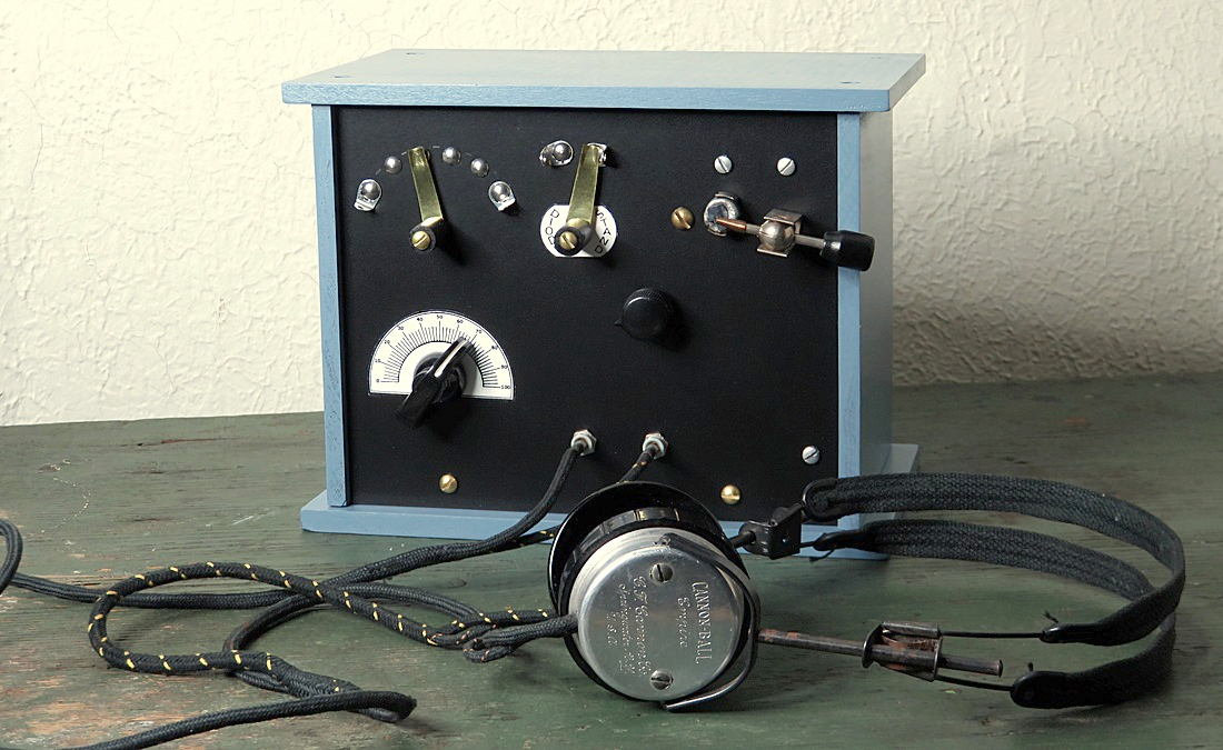
Though a few changes have been made in the layout (it
has a base and the original didn't) the front panel is a duplicate. |
|
|
|
|
|
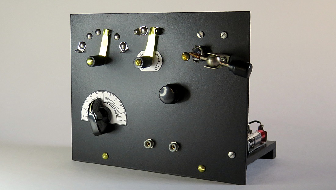
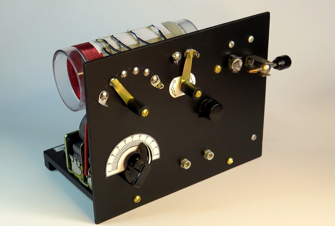
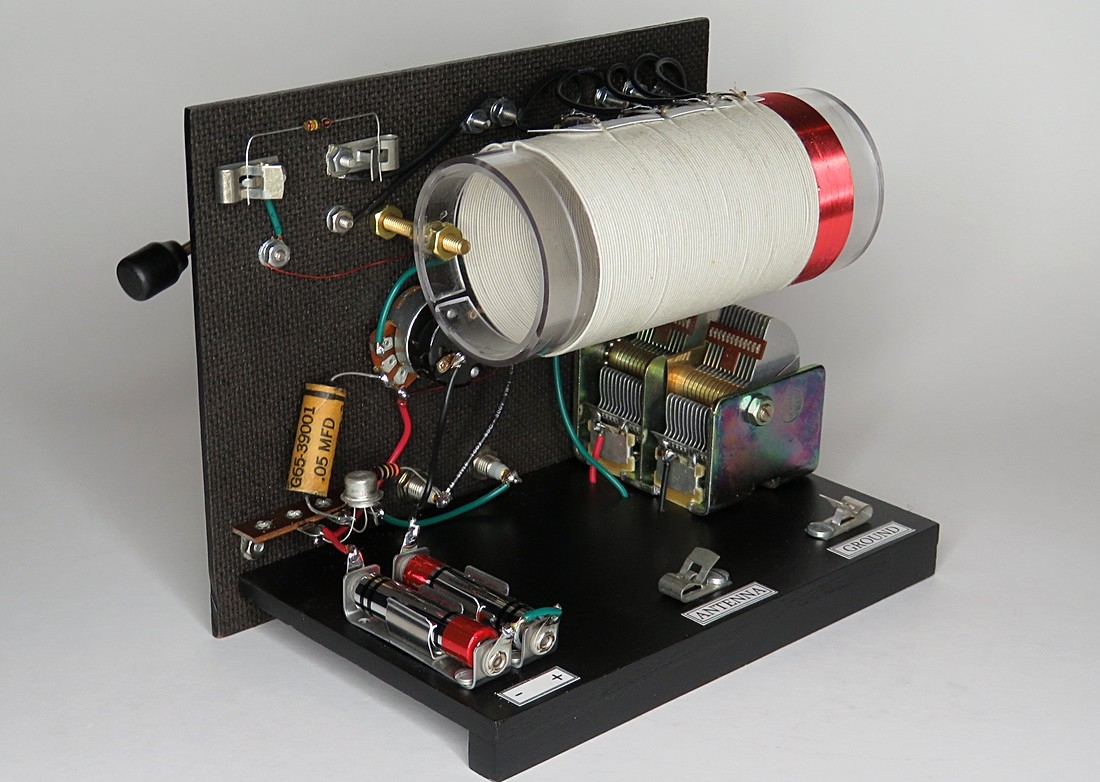
Rear View. The variable capacitor and batteries are
mounted to the base. In the original, everything was on the front
panel. |
|
|
|
|
|
The one transistor amplifier is on the left. Near the
top is a 1N34A diode which can be switched into the circuit from the
front. |
|
|
|
| |
|
|
|
Bottom view. |
|
| |
|
|
| There is one page of instructions to build the set
(MRL Detail Print 34), which can be found
here. |
|
| |
|
| |
|
|
|
|
| |
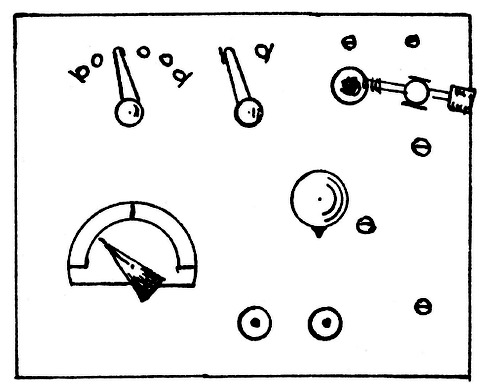
The layout from the plans. |
|
An actual surviving
example from 1972. |
|
| |
|
|
|
|
Without the photo of an original set, there
would have been no way to know this label was part of the
kit. |
|
|
|
|
BUILDING THE RADIO |
|
|
|
|
|
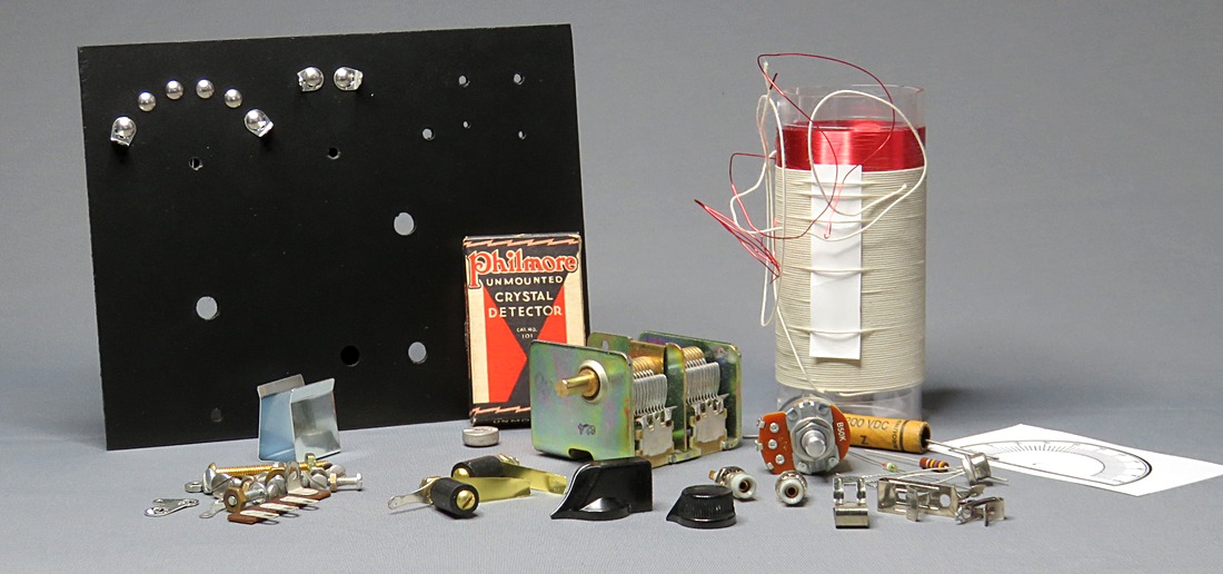
The No. 10 kit purchased from MRL would
have looked similar to this. The panel would already
be drilled, painted and have the switch points
mounted. The coil and switches would be made for
you. A battery, hookup wire, and instructions were
supplied with the kit. It even came with solder. All you had to do was put it
together.
The last of the original kits was sold sometime
prior to 1987. 35 years later it isn't easy or
cheap to acquire these parts. The little box with
the crystal detector was 50¢
in 1986. Today, they are $60.00 and they don't even
come with the crystal. |
|
|
|
|
|
MRL 10-A COIL |
|
|
|
|
|
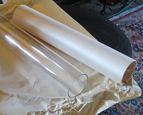
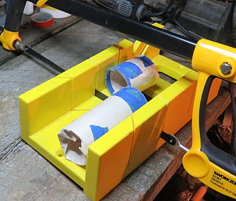
| The coil forms are 2" in diameter
by 4.5" long. These clear plastic tubes were from
ebay and are exactly 2" outside diameter. Each tube
makes 2 coil forms. They were cut by scoring them
all the way around with a hacksaw, as opposed to
sawing right through them. |
|
|
|
|
|
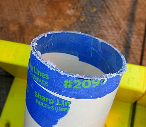
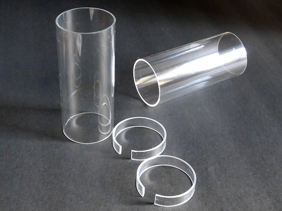
| After cutting the tubes, the ends
were very rough. They were polished by sanding the
ends with an electric palm sander, then wet sanding
them with 800 grit sandpaper. The result was
excellent. On the right are two coil forms and two
reinforcing ends. The reinforcements are purely for
cosmetic reasons and aren't needed with these tubes. |
|
|
|
|
|
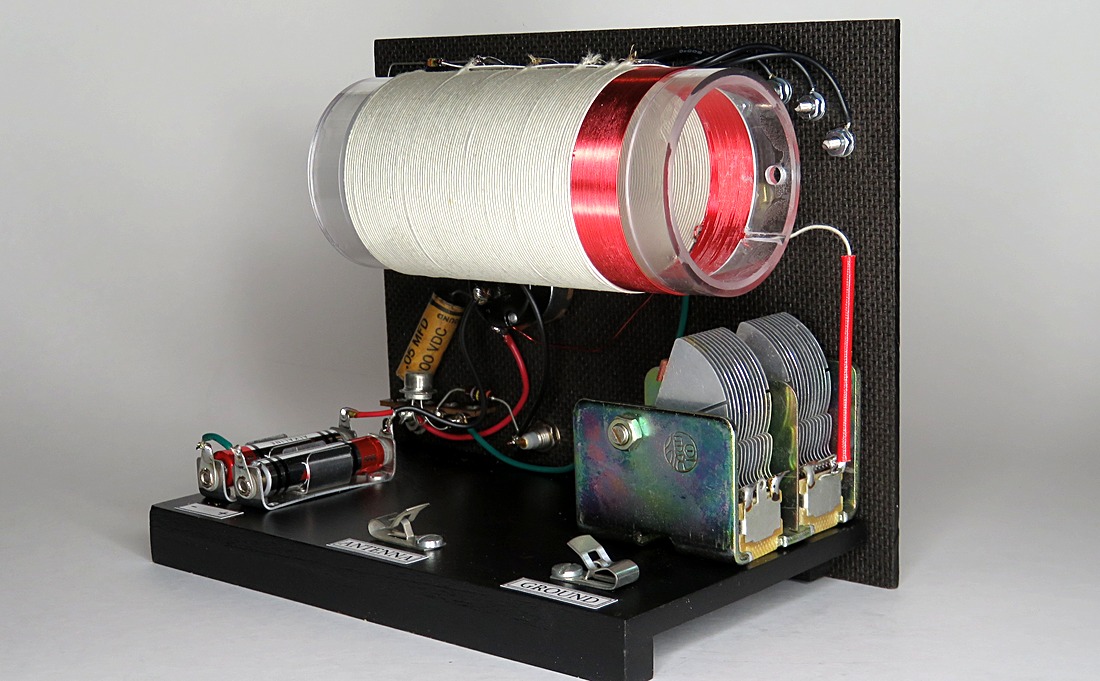
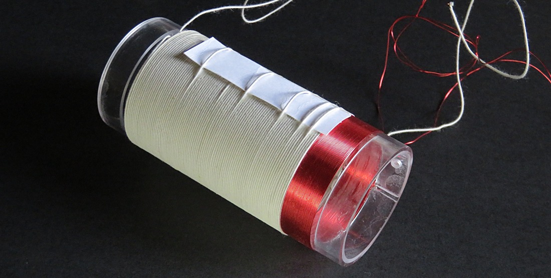
The completed coil. 90 turns of
22 gauge Double Cotton Covered wire tapped at 5, 10,
20, 40 and 65 turns for the primary, and 30 turns of
26 gauge enameled wire for the secondary. Notice my
taps are sticking up in the air. I should have wound
it much tighter, but the cotton covered wire is so
rare and expensive I didn't want to attempt to
rewind it. Instead, I painted it with diluted white
glue (which was what was going to happen to it
anyway).
In the MRL catalog this coil is the #10-A. The plans
give instructions for a "city" or "country" set. The
country version uses the #10 coil. |
|
|
|
|
|
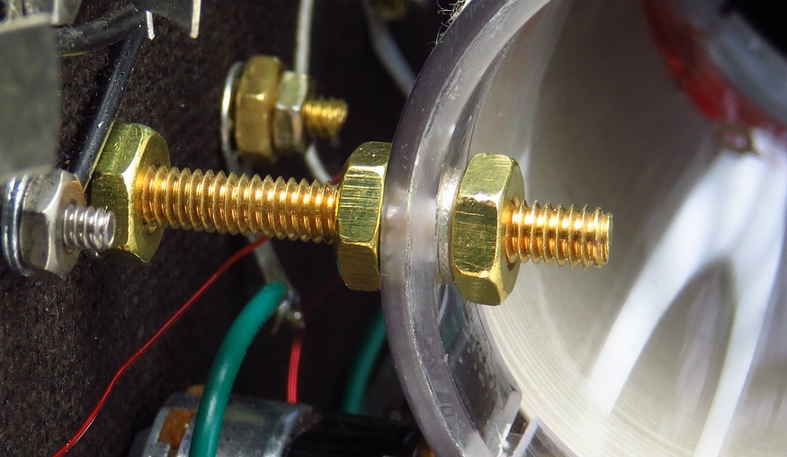
The MRL method of mounting the
coil is also a single point of failure. If the coil
is not securely mounted, it will droop and come into
contact with the variable capacitor. Lock washers
are used at both the front panel and on the coil.
I gave a scrap piece of coil form the "crush test."
A nut and bolt were tightened down in an attempt to
get the plastic to crack, which it did not. I was
then able to mount the coil with two small wrenches
as tightly as practical. |
|
|
|
|
|
SWITCH LEVERS |
|
|
|
|
|
|
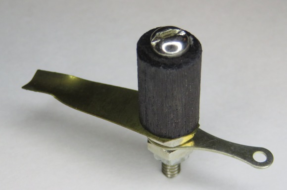
Here are two switch levers made by Elmer
Osterhoudt. He "invented" this type in 1952, after the supply of
antique commercially made switches was depleted. Replicas are needed for the No. 10.
|
|
|
|
|
|
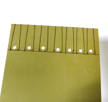
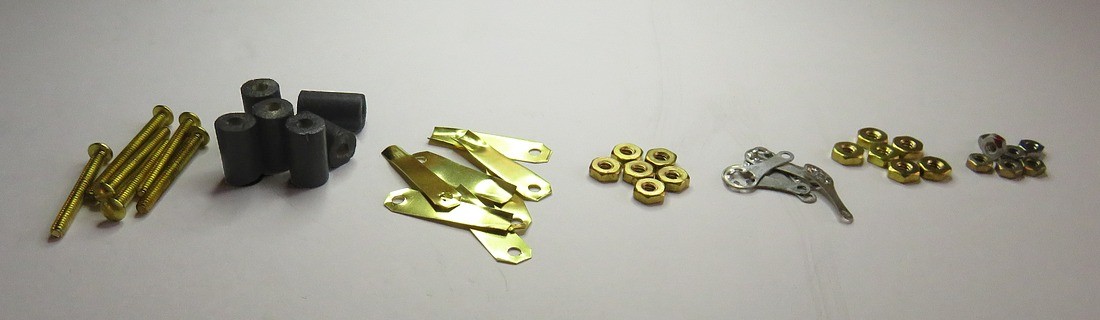
An original MRL switch was carefully
measured to get the dimensions. Knobs were made from
3/8" diameter dowel cut into 9/16" lengths, drilled and painted.
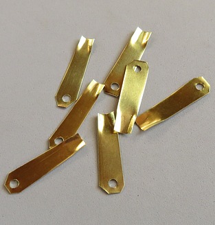
The brass lever is .01" brass sheet from an arts
& craft store. The holes must be drilled in the
brass first, then the brass is cut with heavy
scissors.
I magically ended up with two extra brass pieces. I
could have doubled the amount if I had thought to
measure the lines so they were equally spaced. |
|
|
|
|
|
|
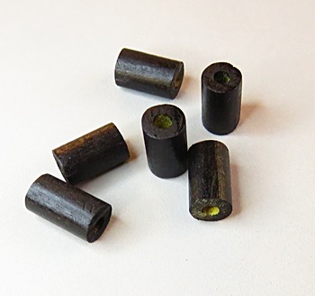
Enough parts for six switches. |
|
|
|
|
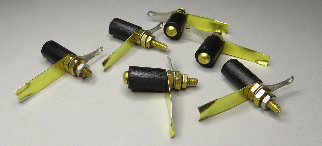
Six replica switches. I don't
know how Elmer made them, but I know how he DIDN'T
make them. He didn't cut the dowel with a hack saw
and throw half the knobs in the trash. He probably
cut a bundle of ten dowels with a band saw and made
100 in the time it took me to make one. I bet he cut
the brass with a heavy paper cutter and made
hundreds of levers at once.
He sold the completed switches for 25¢.
Mine cost more than that just for the screws. |
|
|
|
|
|
|
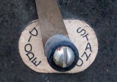
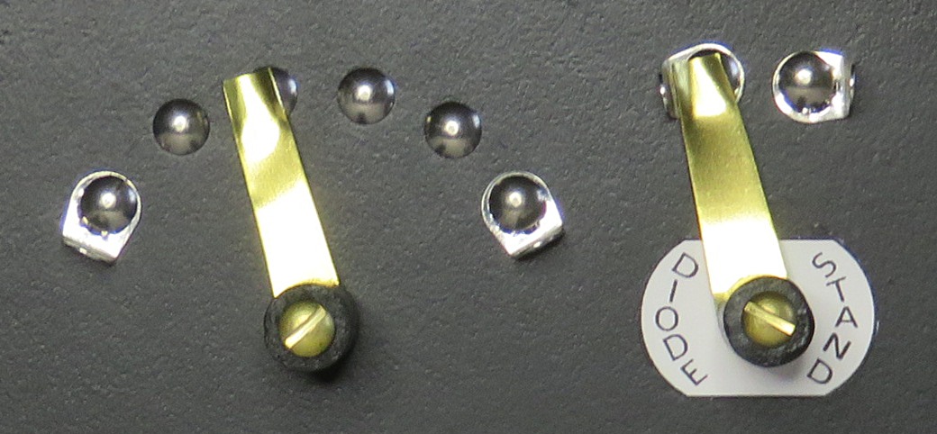
Switches in use. |
|
|
|
|
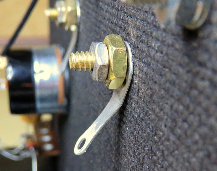
| The switch as seen from the back of the panel. These
switches are the ultimate in form and function. There
is no actual spring on the back, the "springiness" of the brass creates
the required tension on the switch points. You bend
the brass slightly, insert the switch into the
panel, set
the nut on the back till the knob turns smoothly,
then lock it in place with the smaller nut. |
|
|
|
|
| |
|
|
| |