|
Westinghouse
model H-126
"Little Jewel" |
 |
|
|
|
|
|
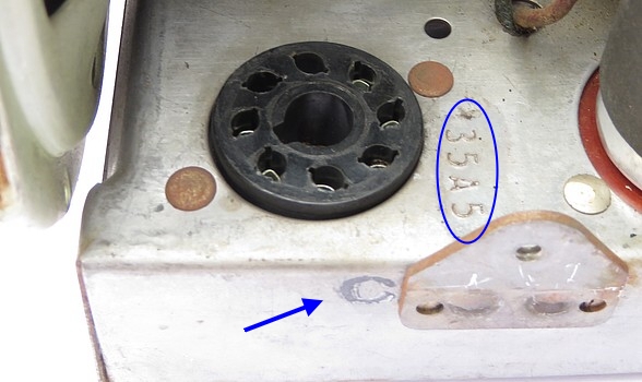
| Dating the radio: These
radios were manufactured between 1945 and 1949. Because of a
scarcity of 35A5 vacuum tubes, the 35A5 tube socket on this
radio has been changed so that it now accepts a 35L6. On the
side of the chassis near the tube socket is the letter "C"
to indicate a change in the design. This change went into
effect either June 20, 1946 or July 11, 1946 (depending on
where you get the information.) Therefore, the radio was made between the
second half of 1946 and 1949. |
|
|
|
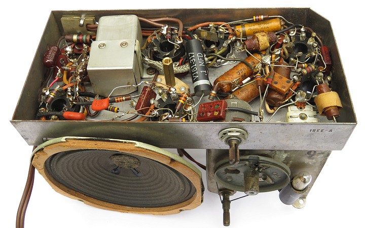
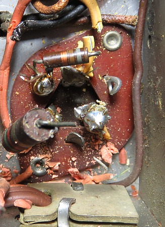
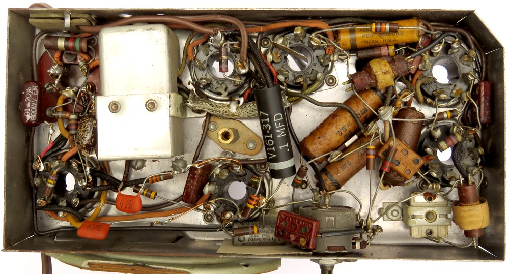
Under the chassis. I "repaired" this in
1987 by replacing capacitors till it started working. |
|
|
|
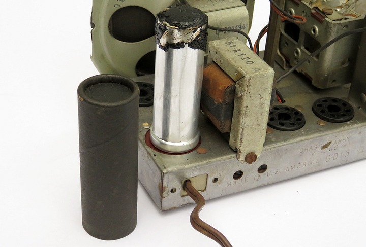
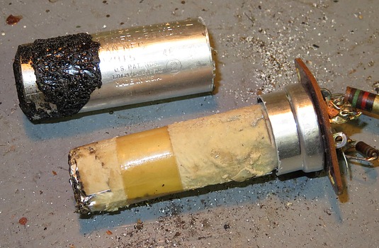
The filter capacitor has a cardboard cover! That
means we can operate on it and then put the cover back on.
There are three capacitors in the metal can. The reason for the
cover is that the can is stamped with the wrong values.
As if there weren't already enough parts in this radio, the
cardboard sleeve had to be added to the metal can to show the
correct values inside.
|
|
|
|
|
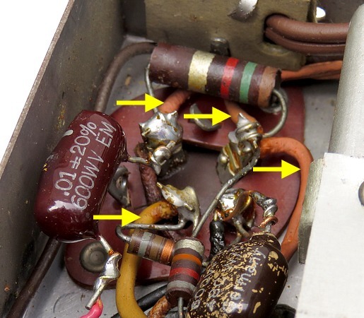
| Connected to the three
filter capacitors are four rubber coated wires that need to
be replaced. The rubber
insulation shattered when I cut the wires. |
|
|
|
|
|
|
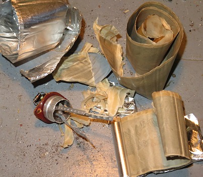
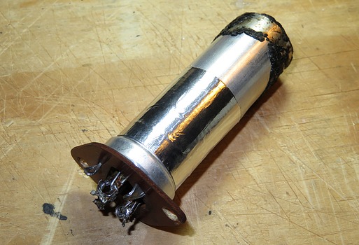
To re-stuff the can, you
need to cut the wires, drill out the rivets, remove the socket with
the can from the chassis, cut it open and pull out the antique capacitors.
In this case, the paper electrolyte material was still sticky. I didn't know what
the sticky stuff was, so I ate some of it to see if it was
toxic in case I had to wash my hands after touching it.
Actually, the sticky electrolyte material is made of Borax
and Ethylene Glycol (anti-freeze.)
|
|
|
|
|
|
|
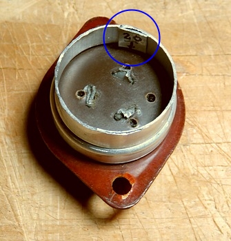
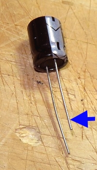
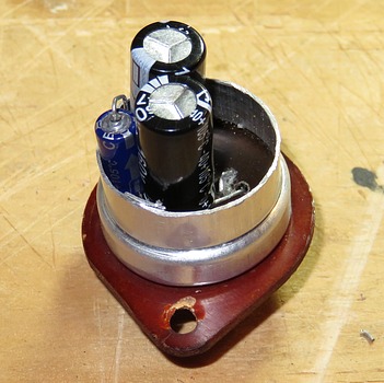
Holes were drilled in
the cleaned-out base for the new caps. It needs two 50uf @
150 volts and one 20uf @ 25 volts. In the left hand
photo I've marked where the positive lead of the 20uf
capacitor goes. If I get this mixed up, 120 volts will go
through the 25 volt cap.
The "clever" plan was to use all 160 volt caps as a
fail-safe. If I got a 50uf cap mixed up with the 20uf cap it
might not make much of a difference as long as they were all
rated at 160 volts. It was a darn good plan if you ask me.
Unfortunately, the negative leads were too short to allow
them to spread out the way I envisioned they would be, so
they are all crammed into one side of the can. I had to use
a smaller 50 volt 20uf cap to get all three of them to fit in there.
So much for my clever plan. Next time I'll find capacitors
with longer leads. *
* A perfect example of a "brain freeze." I
could have soldered wires to the leads to extend them. |
|
|
|
|
|
|
|
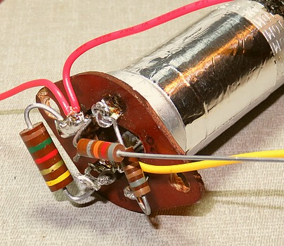
Because the area in the chassis is so
tight to work in, I added some of the components before
putting the can back in place. |
|
|
|
|
|
|
|
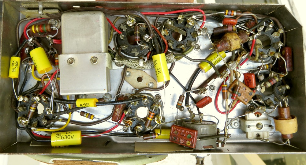
Before and After. |
|
|
|
|
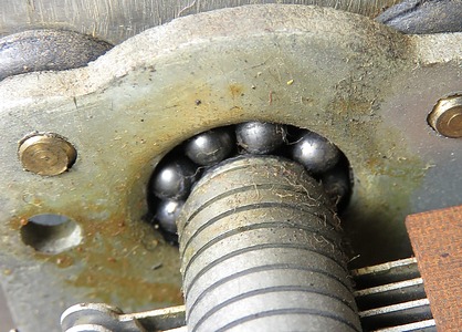
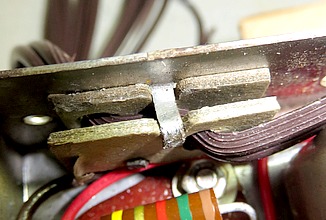
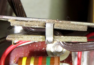
| The bearings in the
tuning capacitor are bone dry, as is to be expected. The
chassis is turned on its side when it's in the case. In this
position, the
12SJ7 vacuum tube is situated directly under the tuning
capacitor and heats it up. The heat from the 35L6 also heats
it up. The grease in these bearings probably melted an hour
after the original owner fired this thing up in the 1940s. |
|
|
| |
|
|
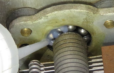
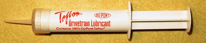
| I used 100% Teflon to
lube the bearings. This dispenser is sold in bicycle shops
to lube bicycle chains. I put some in the toaster oven at
250 ̊ F. It didn't melt. |
|
|
|
|
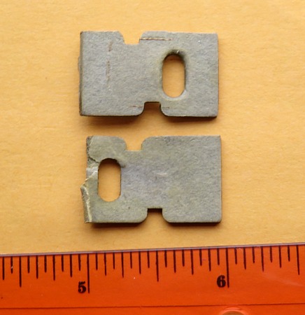
If you are restoring
one of these radios and the strain relief for the AC cord is
missing, this is what it looks like. I believe it was one
piece, with a paper hinge. The fact that it is no longer
hinged makes no difference. You can make these out of poster
board or some other heavy paper material. Notice how they
are keyed and the way the cord is routed.
Mount the cord in the strain relief first, then solder the connections. Or
if you like, you can slide the strain relief parts onto the cord, solder
the cord in place and then attempt to mount the strain
relief. After you realize you gave no thought to the order
the pieces go together, you can cut the cord off and start
over, like I did. |
|
|
| |
| |
|
|
|
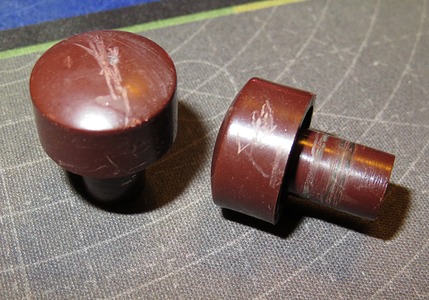
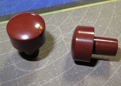
| I let the knobs soak
overnight in soapy water and all those flecks of paint came
off. Once they were clean, the scratches in them became very
apparent. Some 1000 grit sandpaper and plastic polish took
care of them. They look new if you don't get too close. |
|
|
|
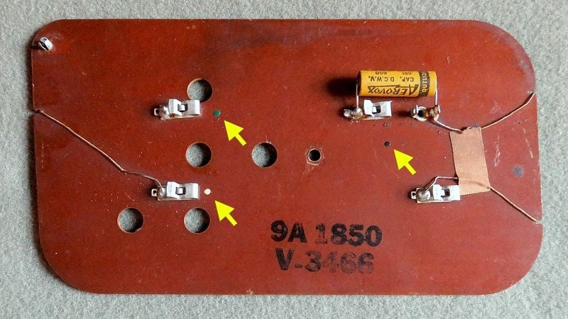
For the sake of appearance, the old
capacitor on the antenna was stuffed with a new one.
There are colored dots to show you where the wires are
connected when you reattach it to the radio. |
|
|
|
|
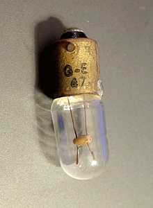
Here's the little No. 47 pilot lamp, made by General
Electric. It looked to be as old as the radio, so it
was replaced. General
Electric was formed in 1892 when the Edison General
Electric Company, founded by Thomas Edison, merged
with the Thomson-Houston Company. A week after this
bulb was replaced, November 13, 2017, General
Electric CEO John Flannery announced that the
company is getting out of the lighting business
after 139 years.
Maybe I should put the bulb back in the radio since
there seems to be some cosmic connection with
current events. On the other hand, GE also made
vacuum tubes. I don't think putting a GE vacuum tube
in the radio would start them making vacuum tubes
again.
Ironically, Thomas Edison invented the diode vacuum
tube and never realized it. |
|
|
|
|
|
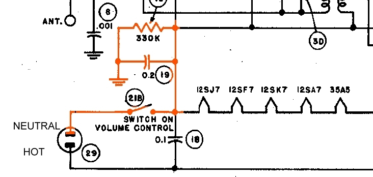
| There is only one route from
the AC outlet to the chassis. A polarized plug was wired as above. |
|
| After checking the resistors,
it was time to plug the radio in and hear how well it works! |
|
| |
|
|
| |