|
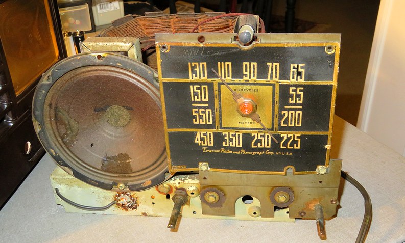
Emerson 330 |
 |
|
|
|
|
|
|
|
| The
77 year old chassis. I glued the cracks in that speaker over
34 years ago. |
|
| |
|
|
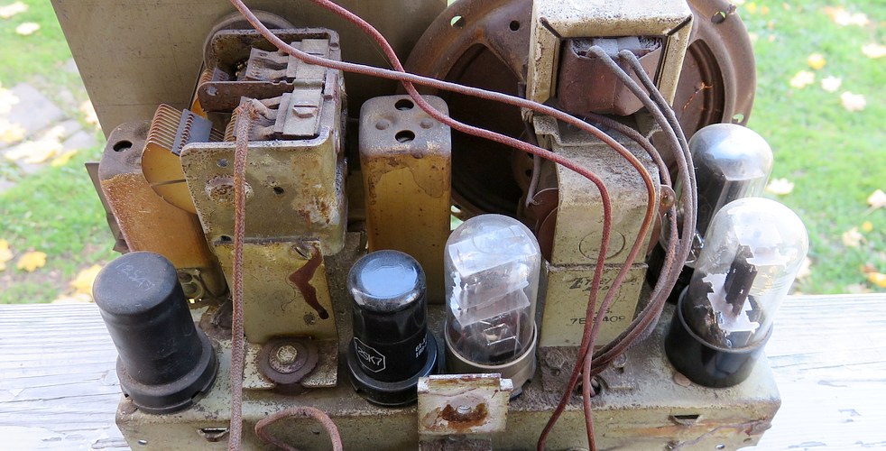
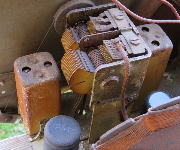
| Here it is from
the back. Look at the glass vacuum tubes. You can see the
tube elements through the glass, even though they are all
fogged on the outside. That should divert your attention
from the rest of the chassis. |
|
| |
|
|
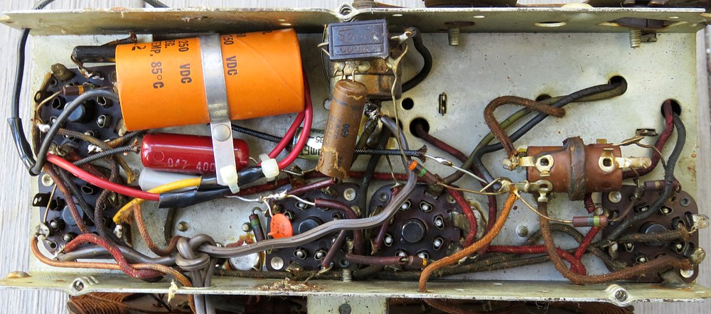
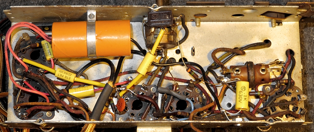
| The underside. It
looks like I had done some work on this, probably to bring
it back to life. Any parts used back then (1980s) were from
stuff I collected as a teenager and should be replaced. |
|
| |
|
|
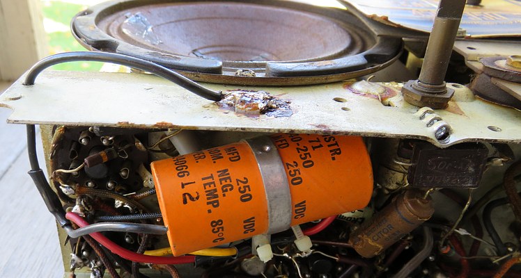
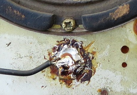
| WHAT THE
DICKENS?!! The filter capacitor wire comes out of a hole in
the chassis and is then soldered to the outside of the
chassis! Did I do that? I don't think so. If
I replaced the filter capacitor, all I did was connect it to
the wires already there. I have no memory of it whatsoever,
but I wouldn't have done it that way. |
|
| |
|
|
| I don't know what
this brown stuff is on the inside. It could be
kitchen grease or cigarette smoke. It likes to stick to aluminum the
best, whatever it is. Maybe it spent its youth in some bar
or the kitchen of a restaurant. If only it could talk.
Obviously, it talks. You know what I
mean. |
|
|
|
|
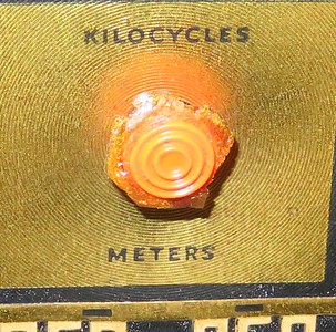
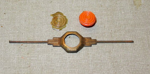
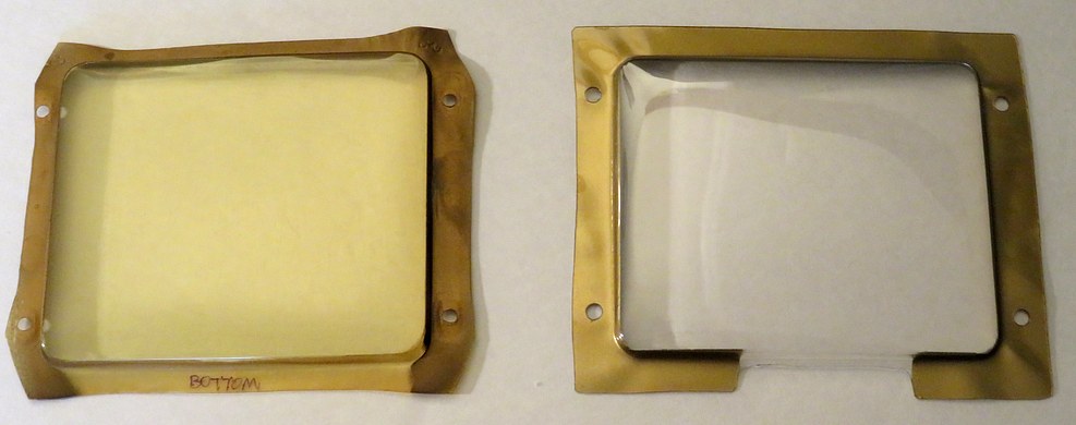
| OK, let's
begin to make some improvements.
First, we'll remove the dial pointer ...aaaaaand it broke.
The first thing I touched. It had broken in the past and been glued back together. The
transparent stuff in the right-hand photo is the glue. This
was actually a bit of luck because it will be much easier to
paint the pointer without the plastic insert. |
|
| |
|
|
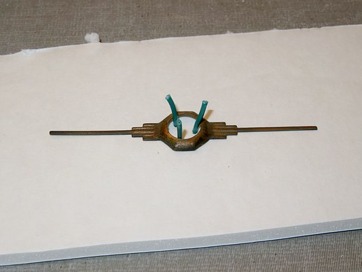
| How the pointer was held during
painting. Otherwise, the pressure of the spray paint would blow it
away. |
|
|
|
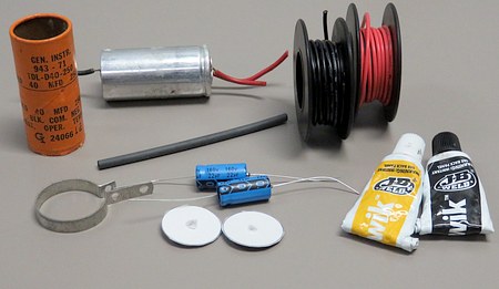
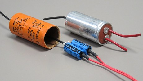
| The filter
capacitors seemed to be working but were the wrong value
(40ufd instead of 20ufd). Here the paper tube is being
re-stuffed with new 22ufd caps. |
|
|
|
|
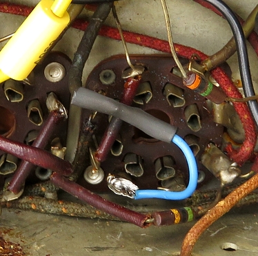
| After the capacitors were
replaced. |
| |
|
|
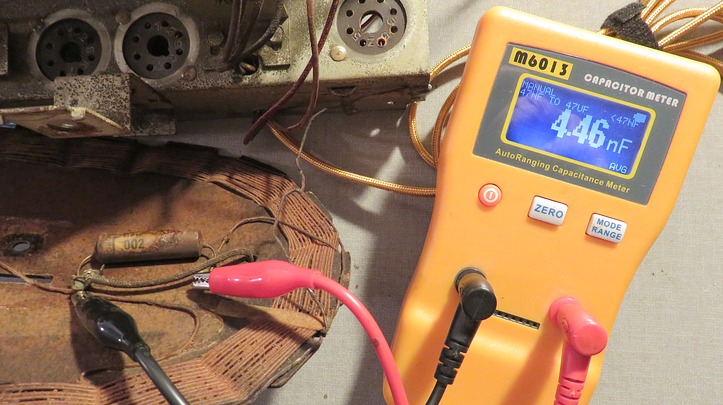
| The only capacitor
not replaced is out of tolerance, but it doesn't matter.
These old radios came with a wire you can clip an external
antenna to. This capacitor goes to the wire. I've found
through experience that it doesn't really matter what the
value is. As a matter of fact, a nice improvement would be
to replace it with a variable one so you could tune the
antenna. |
|
|
|
|
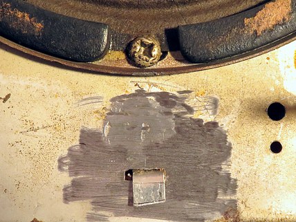
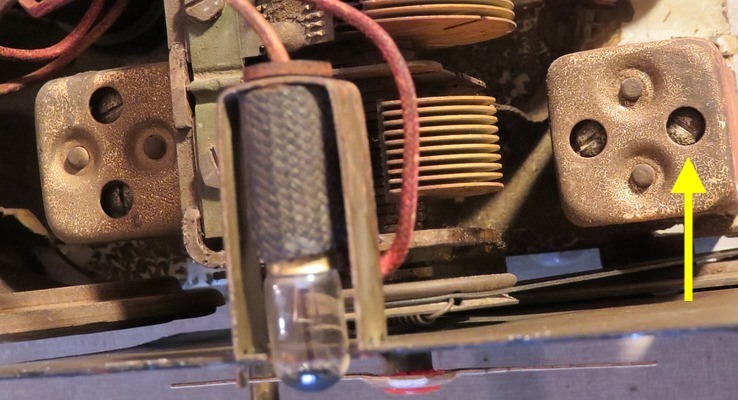
| The "What the
Dickens" solder blob was ground off with a Dremel because I
couldn't find my 100 watt soldering gun. I found the
soldering gun two hours later, after it was no longer
needed (and when I wasn't even looking for it). The metal tab is the holder for the filter
capacitor. I found the tab from the original Emerson filter
capacitor inside the solder blob. |
|
| |
|
|
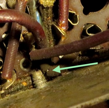
This was the only
hard part. The insulation on this wire (which used to be
blue) is cracked and almost in contact with a screw that
comes through the chassis. There are eight rubber coated
wires in this radio and the insulation on them is fragile.
All eight come from the two I.F. transformers on top of the
chassis.
I decided to leave them alone because I'm lazy. I just cut the wire and carefully
soldered another wire to the end. I don't like the way it
looks but it's only one of several things in this radio that
I don't like. This radio was never made to last for 77
years. |
|
|
|
|
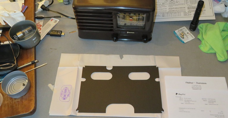
| Time for the new dial cover! (from
dialcover.com) |
| |
|
|
| The dial plate needed some glue. |
| |
|
|
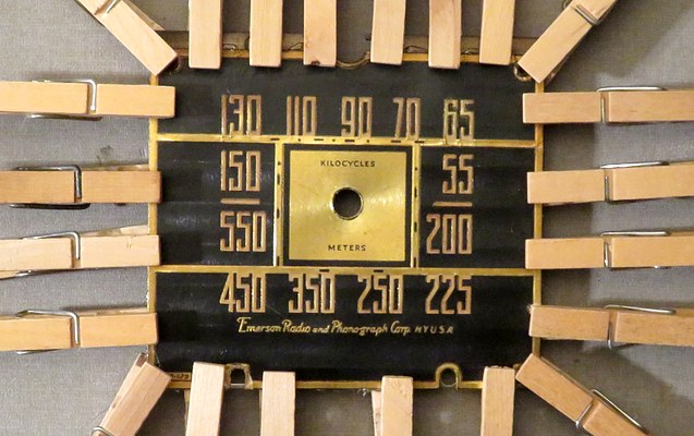
| Now it was time to
tone down the logo. It had been filled with "White Out" and
was way too bright. I used water based paint from the craft
store, mostly white with a little "straw" mixed in. It came
out perfect. I thought of filling it with Testors gold oil-based model paint, because I had some from the dial pointer.
I was glad I didn't. It would have been a mess. While trying
to get the paint in the logo it was all over the place.
Finally, I thinned it, filled in the logo, let it dry
overnight and buffed off the case. It came off very easily. |
|
|
|
|
It was time for
the big test. I plugged the beautiful gold cord into the
outlet and turned the radio on. The pilot light came on
brightly and then dimmed - a good sign. I let the set warm
up, but didn't hear anything. I turned the volume up and
started tuning around, but still didn't hear anything. Then
a faint squeal came in from a local station. Hmmmm... it was
working before I "fixed" it.
The schematic said the first IF transformer was on the
right. I turned the right hand trimmer screw about 1/16 of a turn
and the whole dial came to life! Whew!! I adjusted all four
trimmers for maximum signal. |
|
|
|
|
|
|
| |
|
|
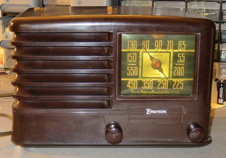
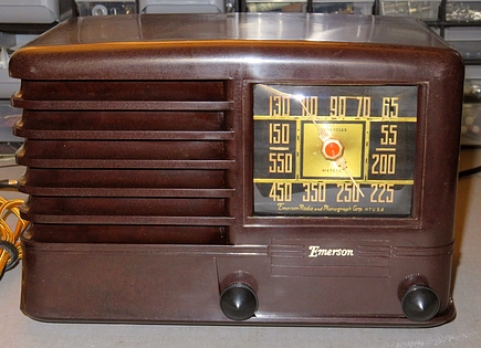
| Before and After. |
|
|
|
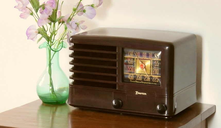
| Unless a calamity
occurs there is no reason this radio won't be working on
its 100th birthday. Will there still be AM
radio in 2039? |
|
|
| |
|
|
| |