|
Lance Borden "Armstrong one tube
Regenerative Receiver"
Review |
 |
|
|
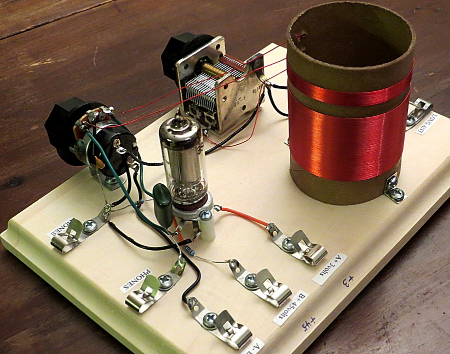
As
stated on the Borden Radio website, the kit contains all high quality
parts. The pre-drilled base is furniture grade pine, and the heavy
cardboard coil form is already coated in polyurethane. All parts are
included, even the hookup wire and felt "feet" for the bottom. You'll
need to supply your own batteries; two "D" and five 9 volt.
|
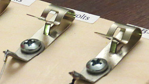
| Solder lugs
are included with the kit to make hookup easy, and the connections will remain
tarnish free for the life of the set (virtually forever.) The labels are also provided. |
|
|
|
| The kit comes
with a ten page pamphlet. In this pamphlet, along with the instructions
to assemble the kit, are a brief history of the vacuum tube, early
radio development and notes on Edwin Armstrong and his invention of the
regenerative radio receiver. There is also an explanation of how the
radio works, what the vacuum tube does, and how to operate the radio.
There is a very nice schematic diagram of the radio with a parts list,
all on one page. |
|
|
| Many one tube regen
radios have 45 to 90 volts B+ going through the headset. This one
doesn't. There are no problems
with stray capacitance in the headset cord to throw you off while
tuning a weak station. Also, an audio amplifier can be connected
without altering the circuit. It is surprisingly immune to hand capacitance
while tuning it. |
|
|
|
|
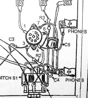
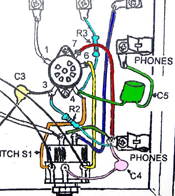
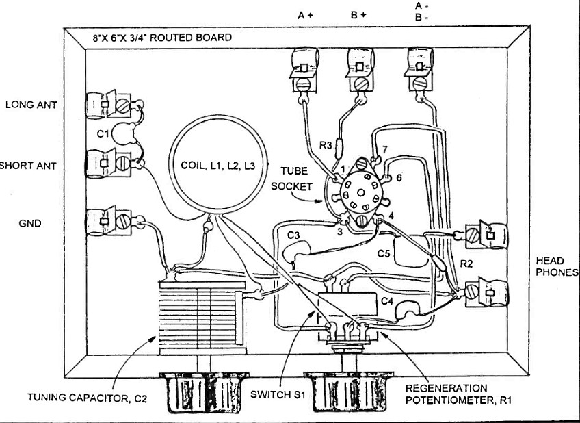
| Assembling the
set was a bit of a challenge because of the instructions. The image to the left is a part of the
wiring diagram. Try to find capacitor "C4" in the drawing. This, and a black and white photo are what you use to
wire the set. We ended up referring to the schematic diagram time and
again. Adding color and moving C4 and C5 in the drawing makes it readable. |
|
|
|
|
Illustration from Electronics
Handbook Vol. XIX
|
If you contact Lance
Borden he'll send you a copy of the magazine article he
wrote for "Electronics Handbook Vol. XIX." In it is a much clearer
drawing of the radio. Unfortunately, we didn't have this at the
time.
UPDATE: See the link on the previous page to view the magazine.
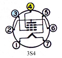
Actually, pins 3 and 4 are reversed in this drawing (observe
the connection of R3 in upper drawing), so perhaps it was good that
we followed the schematic. The kit came with a 3S4 vacuum tube. The drawing in the magazine uses a 3A4 tube, ergo the reversed
connections. |
|
|
|
|
|
|
|
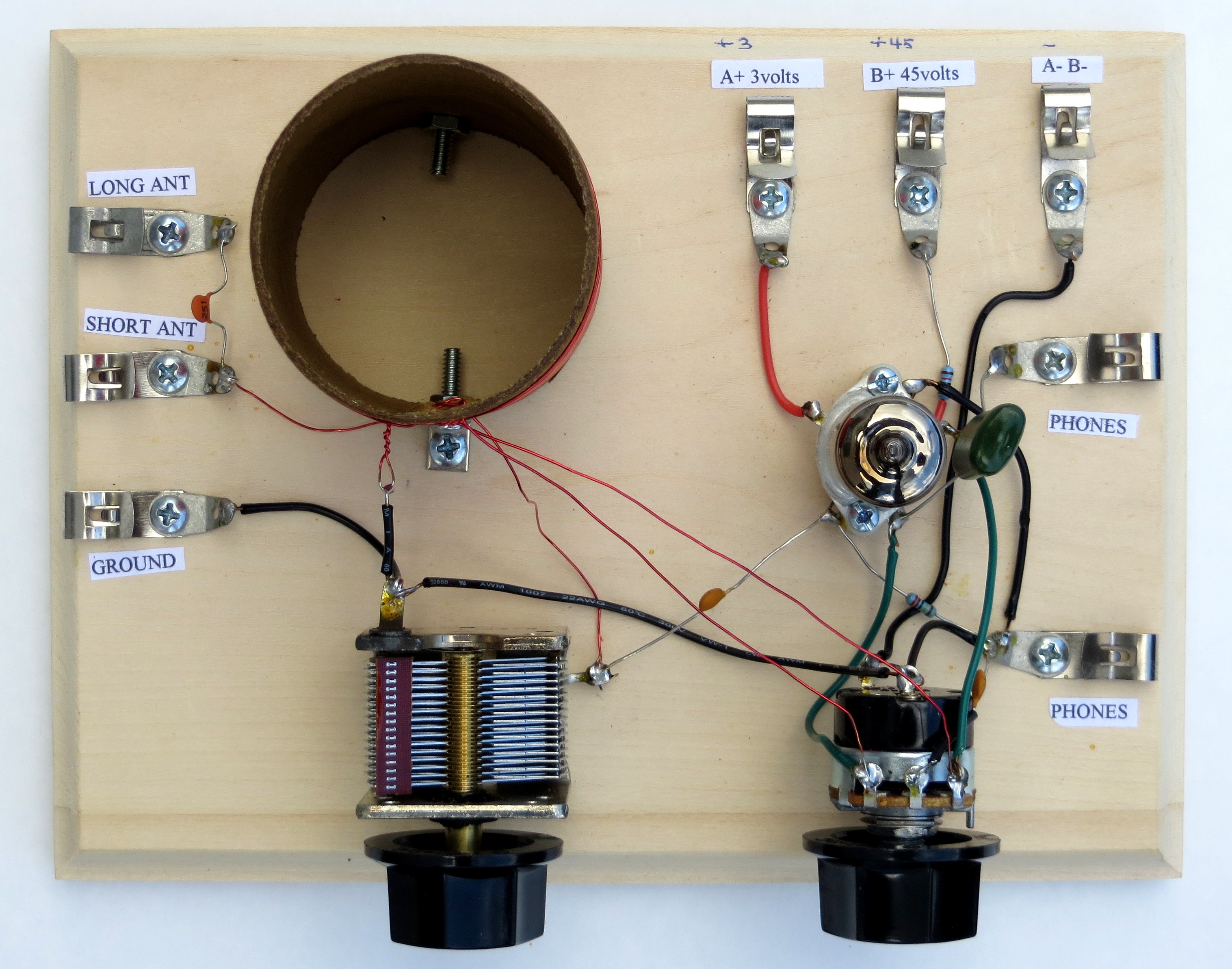
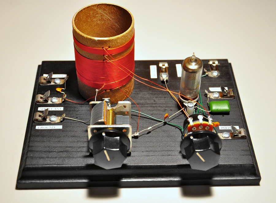
Finished Radio. (Click to enlarge) |
|
|
|
|
|
|
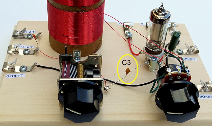
Construction tip - place the variable capacitor on the
board so that capacitor C3 can reach it. |
|
|
|
| Now we come to
an unexplained problem with the set. The low station on the AM dial
here in the Philadelphia, PA area is WFIL, AM 560. The radio wouldn't
tune down that far. Why not? Did Matt miscount the turns while winding
the coil? The number of turns on the coil were counted THREE times and
were found to be perfect. (20 turns, a tap, and 55 turns, for a total
of 75 turns of wire). So what exactly was it tuning down to? |
|
| |
|
|
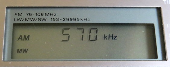
| That was easy to
figure out. A regen radio transmits on whatever frequency it's tuned
to. All that was needed was to use a radio with a digital display and
listen to the squeal from the regen radio. In this case, it tuned down
to 570 kHz. |
|
|
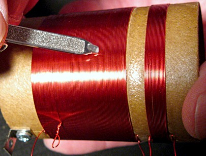
| Method used to
count the turns of a coil: A blunt hard object is wiped over the wire
and the number of "clicks" are counted. (The corner of a credit card
works well.) This can be an exercise in concentration! It is also
useful while winding the coil if you become distracted while counting.
In this case,
the number of turns was exactly what the instructions called for.
20 turns, a tap, then 55 more turns.
|
|
|
|
| After looking at
some radio websites and online coil calculators, it became apparent
there weren't enough turns to tune down to the low end of the band. The
coil was removed from the set and a new coil was wound on the same coil form. The
new coil has 21 turns, a tap, and then 61 more turns, for a total of
82
turns. 26 gauge wire was used, same as the original. |
|
|
With the new coil, the
radio tunes from 540 to 2000 kHz. I was surprised to hear Morse code
up at the higher end.
The big question is this: Do every one of these Borden radios have the
same problem? There are photos of seven completed radios of this design on
the xtalman website, and in 2004 the set appeared in CQ Amateur Radio
magazine. Perhaps hundreds have been built. Did we get the oddball?
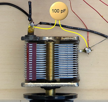
It turns out we didn't. In a radio forum a guy asked
why he couldn't tune in a station at 580 kHz on the set. One answer
was to put a capacitor of 100 pf across the tuning capacitor.
That would be easier than rewinding the coil!
|
|
|
|
|
|
|
Like this. |
|
|
| Well, it works now. Troubleshooting this was all part
of the fun of building it! |
|
|
|
|
|
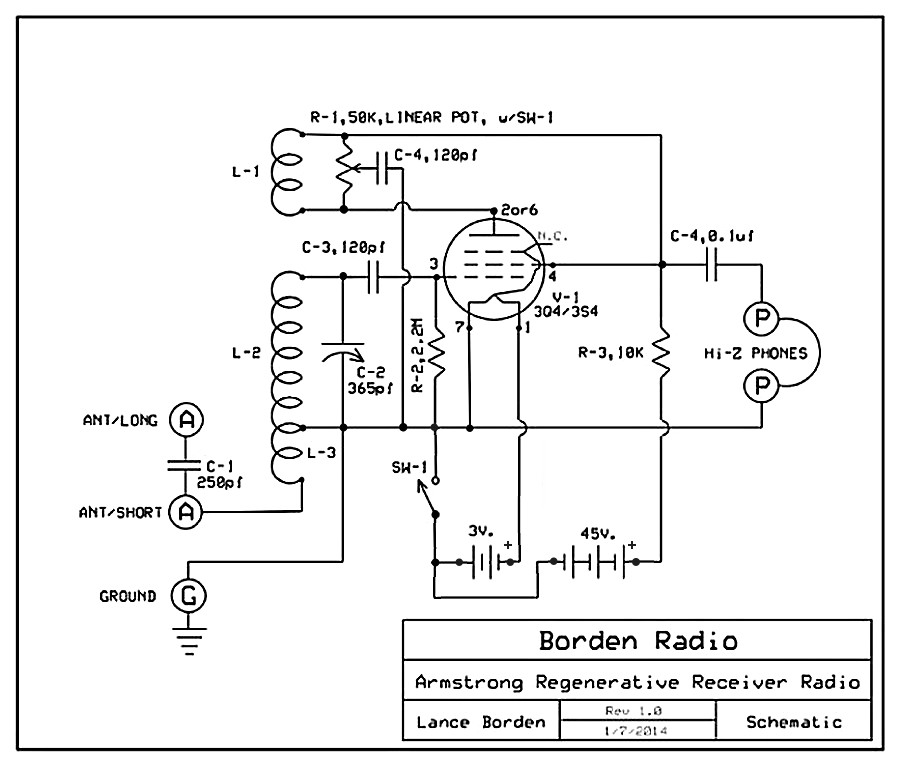
The schematic, drawn by
Mike Peebles. Number of turns for 2"
diameter coil.
|
|
| Note: if using a 3A4, connections on
pins 3 & 4 of 3A4 tube are reversed compared to 3S4/3Q4. |
|
|
|
| |
|
|
|
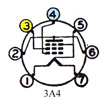
| |
FYI, tube diagrams
show the pins as viewed from the bottom of the tube.
Pins 3 and 4 are reversed on 3A4 vs. 3S4 as noted above.
The 3A4 was designed 2 years after the 3S4 and has a higher output. |
|
|
|
|
|
A Borden clone with alternative filament hookup.
The "Shoelace Radio" |
| "\Milorad" built this
clone using a 3A4 tube. The object on the right is an impedance
matching transformer for the headphones. |
|
|
|
|
|
|
|
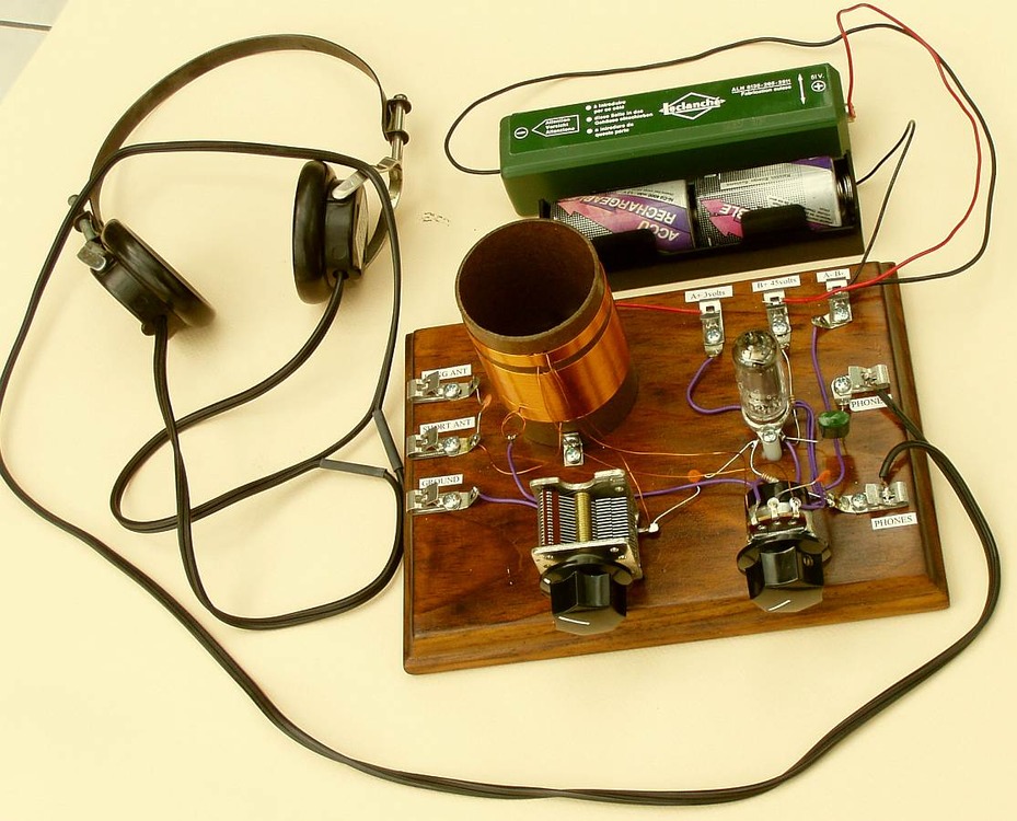
The radio as built by Lance Borden, from the cover of
Electronics Handbook magazine, |
|
|
|
|
|
|
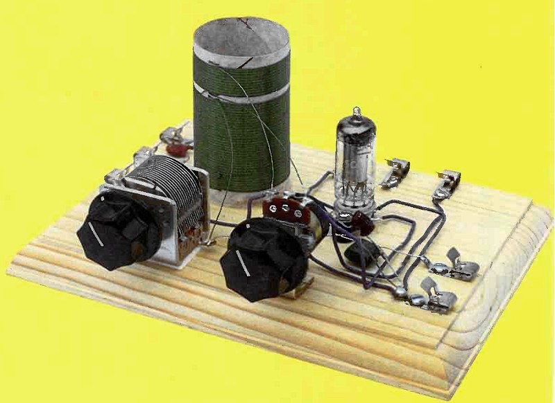
This beautiful set was built by Felix Schaffhauser of
Switzerland. |
|
|
|
|
|
|
A painted base. Very nice! |
|
|
|
|
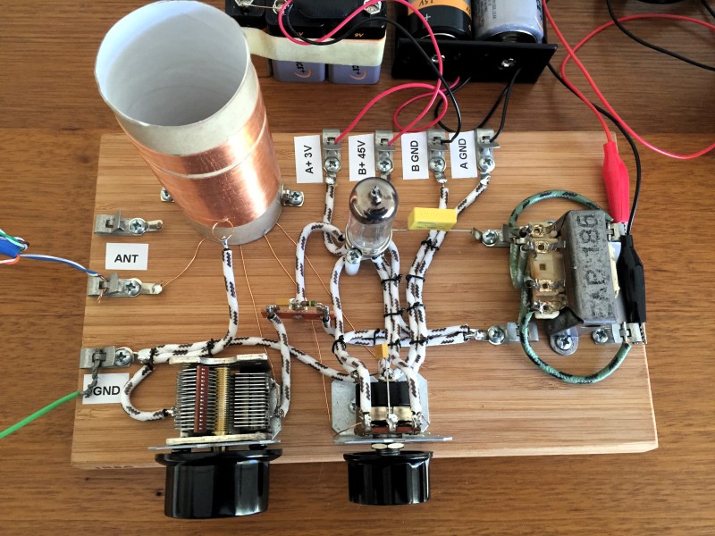
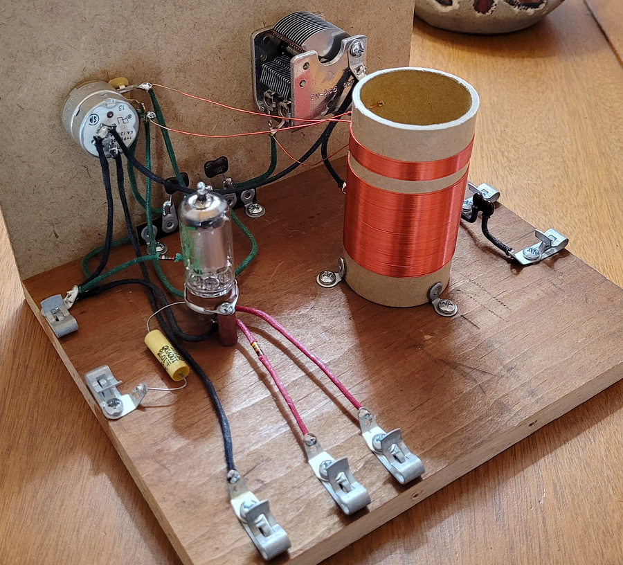
B. Matteson built this home-brew version. Notice how
uncluttered the wiring is with the addition of a front panel.
Coil Data:
Wire: 26
AWG enamel coated solid copper
Diameter 1.65 inches
L1: 17
turns
L2: 67 turns
L3: 23 turns
Frequency response: 550 -
1700 kHz |
|
|
|
|
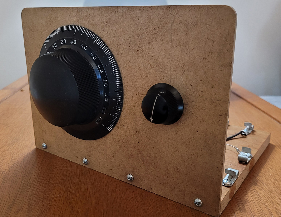
Front view. |
|
|
|
|
|
|
|
| |