|
|
|
Repairing Philco wet electrolytic filter capacitors |
|
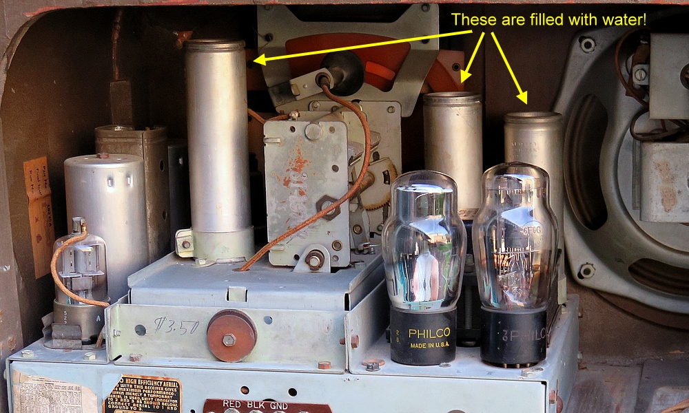
| Some radios need a
cup of water to make them work. |
| |
|
|
|
| In the 1930s
and '40s some radios had filter capacitors in the
power supply whose electrolyte was mostly distilled water.
They are known as "wet electrolytic" capacitors. I
find it amazing that water is a component of
the radio set. |
|
|
|
|
|
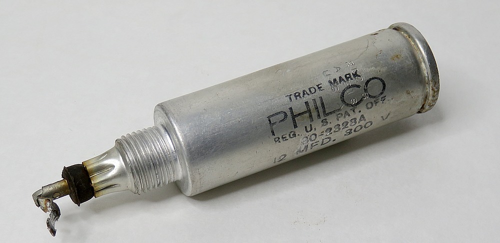
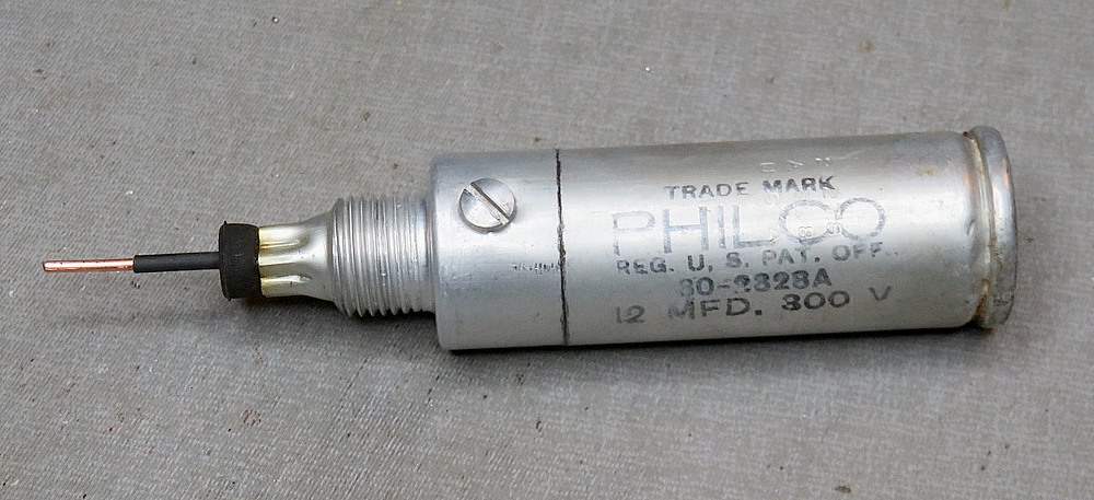
Here is a 1939 Philco "wet" capacitor. Freed from the chassis after 80
years, most of the water in it is gone.
Can we fill it back up? No* but
what follows is a suggested way to repair it.
|
*
Theoretically, you could drill a small hole in the end-cap
and use a syringe to refill the can. I wasn't going to
attempt it, or use the radio
with a compromised filter capacitor. |
|
|
|
|
|
|
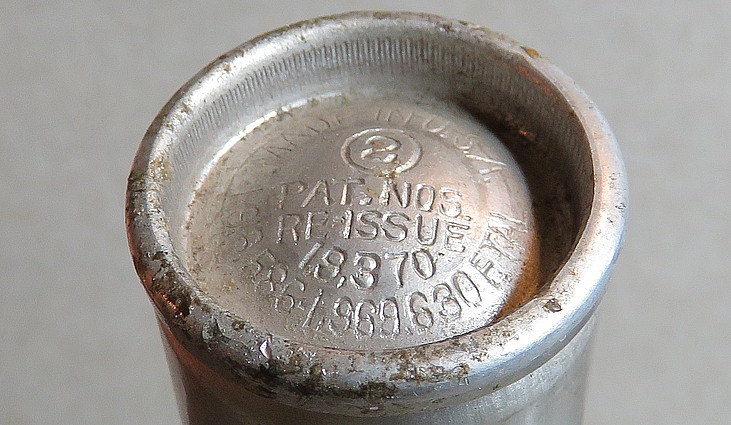
ADVISORY NOTICE: Please be aware
there may be some pressure inside the capacitor. The patent
stamped on the end cap (which is actually the patent for the
end cap, not the capacitor) describes how it is shaped a
certain way so the pressure doesn't blow it off. Most of
this pressure is generated by heat radiating from the vacuum
tubes while the radio is on.
Patent No. 1,969,630 can be seen
here. |
|
|
|
|
|
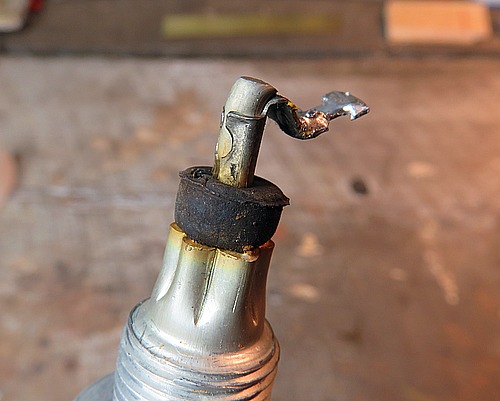
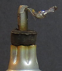
If the capacitor
has a crimp-on connector, just cut it off. You can try to remove it,
but I couldn't get mine off the wire without chewing it up.
I didn't put much effort into it, I admit.
So to start, draw a line around the outside of the capacitor about 3/4
inch from the bottom end. Gently work around it with a
hack saw till you cut through the can. Don't cut right through it as if it was a piece of
pipe. Have paper towels under the work. |
|
|
|
|
|
Once you cut
through in one spot, any liquid still inside will come out.
Have extra paper towels standing by in case you have a full
one. Ironically, a full one probably works perfectly but
there is no way to determine how full it is without cutting
it open. That's OK, the odds of finding a full one are
miniscule.
Notice on the left photo there is a pencil mark
perpendicular to the cut. This is to help align the parts
when they are put back together. |
|
|
The electrolyte is a combination of
distilled water,
boric acid and ammonium borate. You can get it on you, but don't
drink it. If you have an urge to drink it, seek immediate
psychiatric care.
The electrolyte is very
pure. The slightest trace of contaminants would have
affected the properties of the capacitor. It has a distinctive
odor, which for some reason I keep smelling. |
|
|
| |
|
|
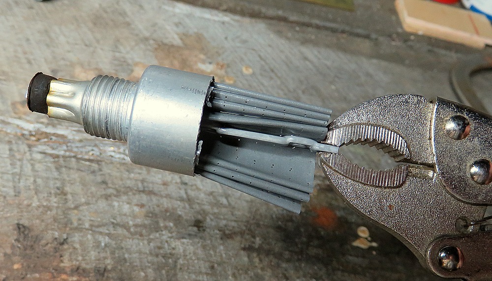
| This is what was inside.
The cylindrical screen is plastic. It insulates the center
electrode from the aluminum can. As a matter of fact,
nothing touches the can but the water, yet the can is the
negative side of the capacitor. (Not all Philco capacitors look like this inside.) |
|
| |
|
|
| Grab the center electrode
with pliers and pull it out of the rubber stopper while
twisting it back and forth. |
| |
|
|
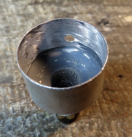
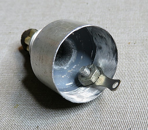
Sand the inside of the
bottom piece down to bare metal, drill a hole, and attach a
solder lug.
Make sure it is tight; 200 - 300 volts will be going through
it. If you don't have a solder lug, use a piece of wire. |
| |
|
|
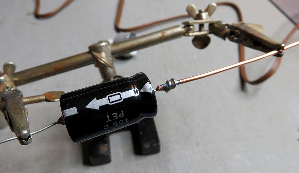
| Take your replacement
capacitor and solder a piece of heavy wire to the POSITIVE
side. This is 14 gauge from some house wire. |
| |
|
|
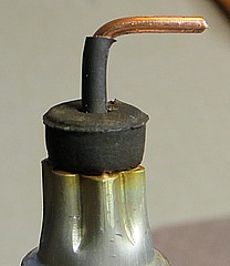
| Insert the heavy
wire into the rubber stopper till the new capacitor is
seated. Mark the wire a bit above where it exits, remove it, then apply
heat-shrink tubing up to the mark. Reinsert the capacitor
and solder the negative end to the solder lug. You now have
a working replacement Philco capacitor. |
|
|
| |
|
|
| Next we need to put the two
halves of the aluminum can together. You will need a
thin cardboard tube. In this case, the diameter of
the tube was too large, so it was cut down the back
and overlapped. A cutout is needed to clear the
solder lug. |
|
| |
|
|
| Next, glue the cardboard tube
inside the bottom part of the housing. I used J-B
KwickWeld. Use whatever you want that works. |
|
| |
|
|
When the glue has set on
the bottom half, glue the top half on.
Black epoxy made a black seam. Next time, I'll use clear.
If this needs to opened again,
it can be cut with a utility knife along the seam.
That thing looks a medical device in a sci-fi movie. |
|
|
|
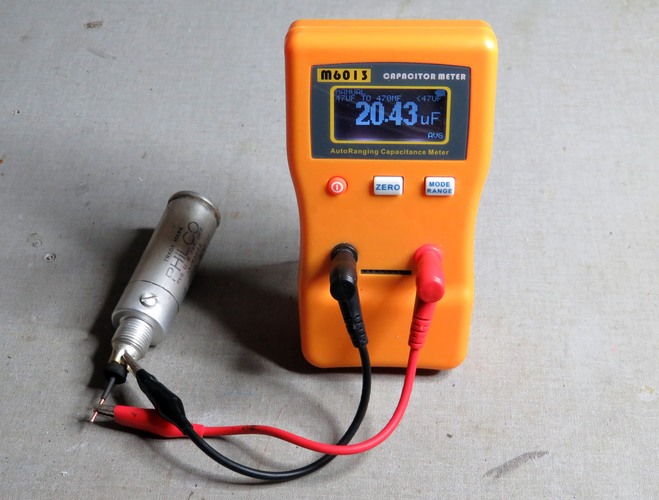
If you are able, test the
capacitor before it goes back into service. Bend the anode
so the wires will be soldered in the exact same place as
before.
Mark the can with the new value and the date. Don't use a
felt tip marker because the ink will fade over the years. |
| |
|
|
Note 1: This particular capacitor
was rated at 12 mfd. They don't make 12 mfd capacitors
anymore, so I used a 22. I could have used a
10 mfd and a
4 mfd in parallel to make a 14. Also, two 22 mfd in
series would have made an 11 mfd. I was too lazy.
Note 2: Obviously you need to observe the voltage.
The original was rated at 300 volts. I used a 450 volt
replacement. |
|
|
|
|
|
|
|
|
|
Cutting the capacitor in half is
OK if you are going to repair or refurbish a radio.
But what if you want to RESTORE the radio? Steve
Geary wrote in with this method. Hold the capacitor
in a lathe. While it is spinning, cut
it at the crease to the end cap by holding an X-ACTO
knife against it.
He uses aluminum solder and a butane torch to add a
small pool of solder to the inside of the can. The
negative side of the replacement capacitor can then
be soldered with regular solder to the aluminum
solder. When the top is glued back on, it's not
apparent that it was ever opened.
Steve knows a little about radios.
He built a "barn" just to house them all. |
|
|
|
|
|
|
|
|
|
Where do you get capacitors now that Radio Shack is
closed? You can usually find them along the side of the road after
it rains. |
|
|
|
|
A Philco capacitor water bottle!
Somebody make this so I can get one. Since it's my idea, I expect a
free one. |
|
|
|
| |
|
|
| |